Project 1970 Camaro SS Part 2
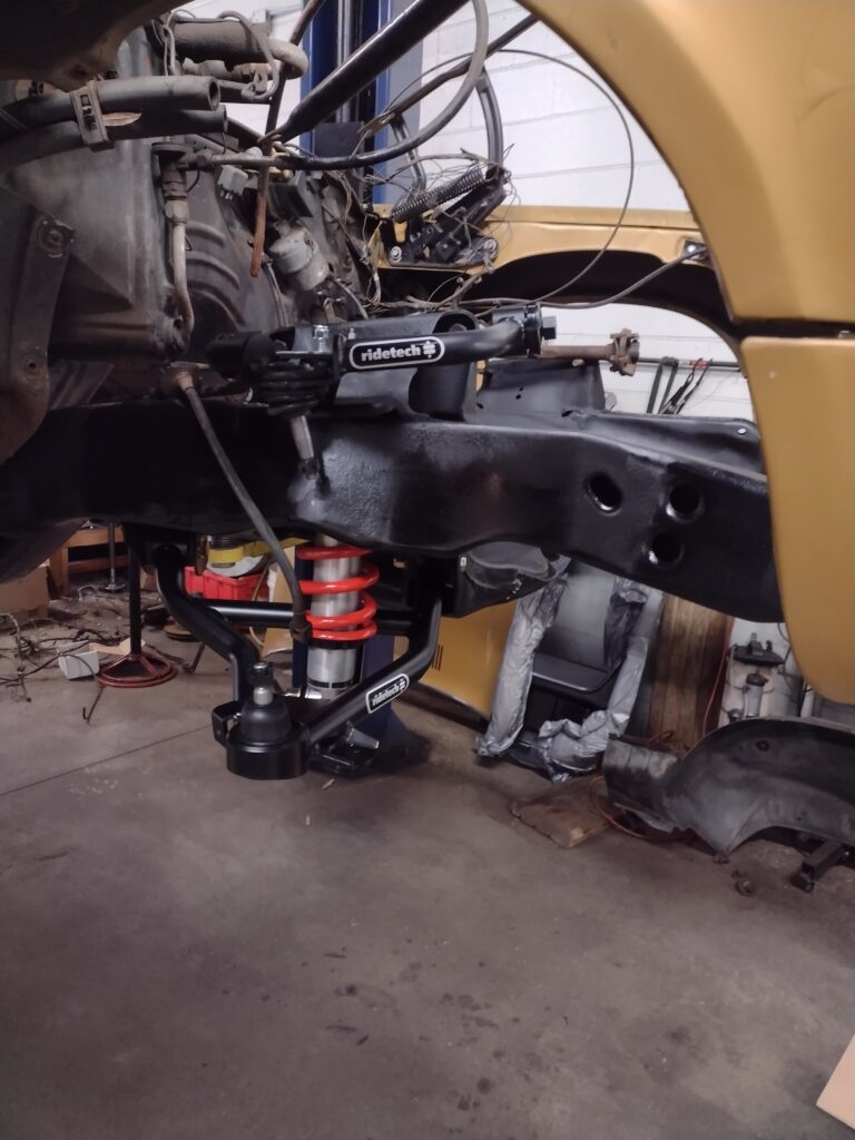
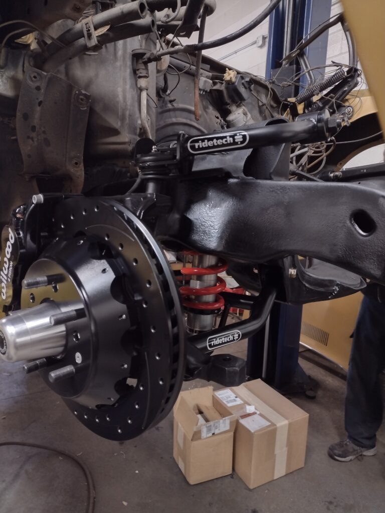
In Part 1 of this build story we removed the powertrain, exhaust system, front and rear steering and suspension, fender liners and radiator support, cleaned and painted the frame. Now, we are ready to install the new Ride Tech upper and lower control arms, coil overs, and get ready to mount our original spindles which have been thoroughly cleaned, rust removed, and repainted.
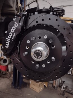
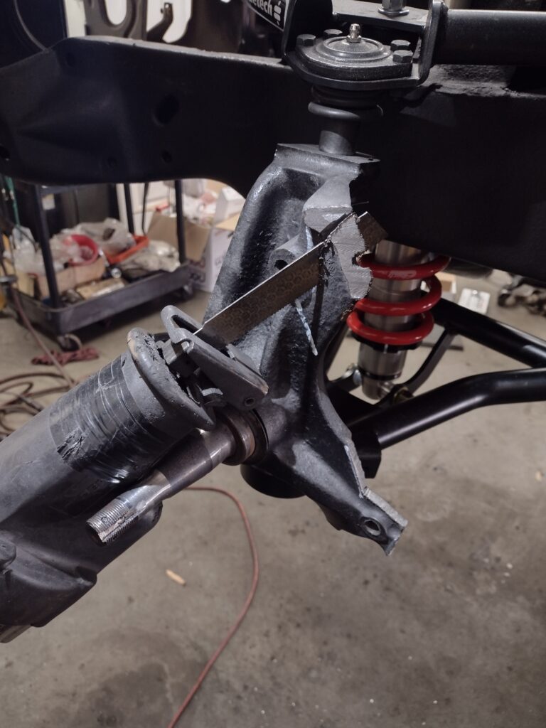
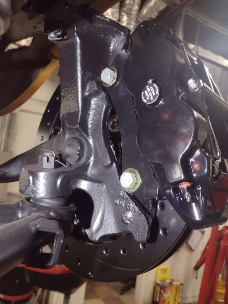
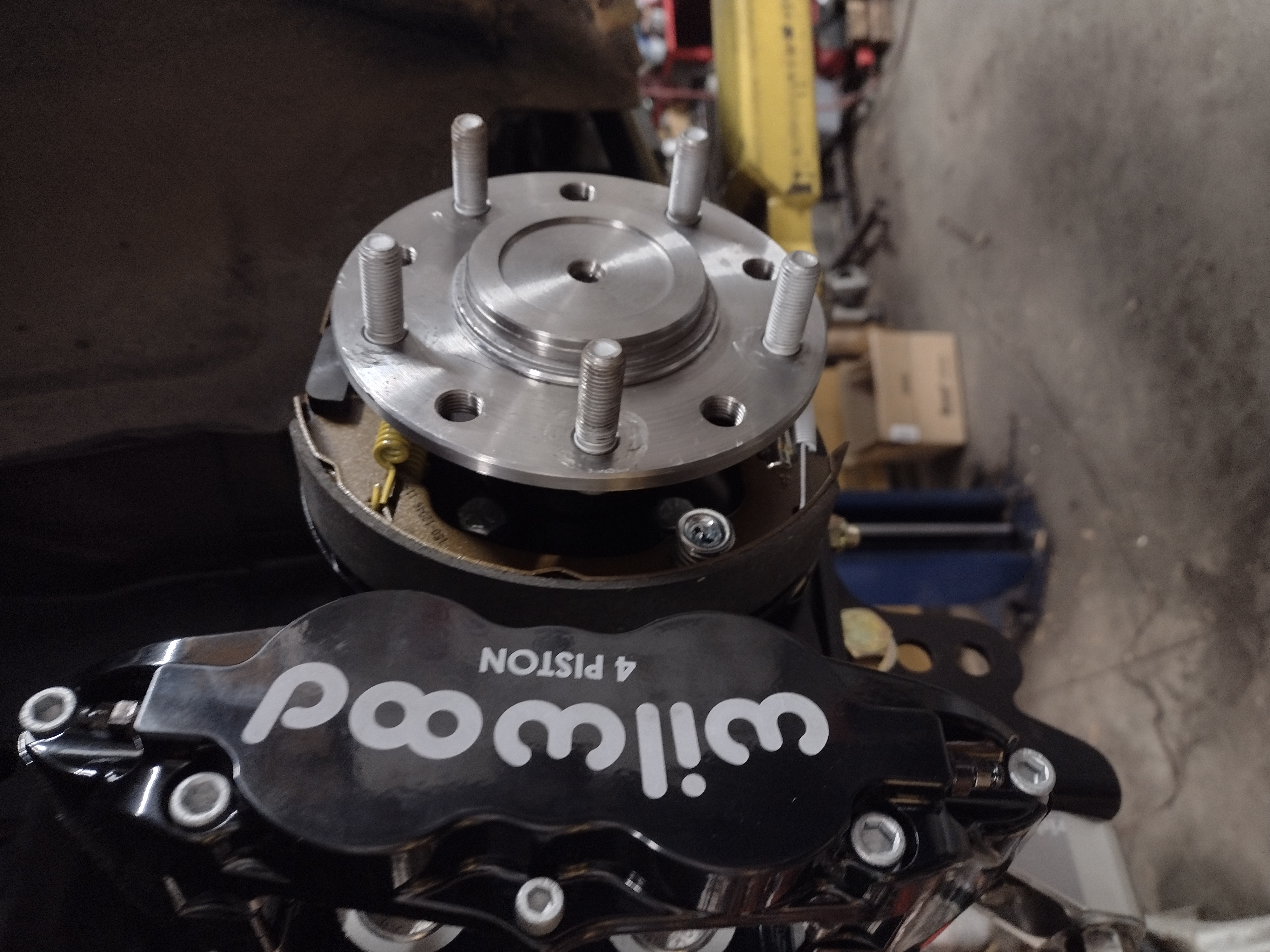
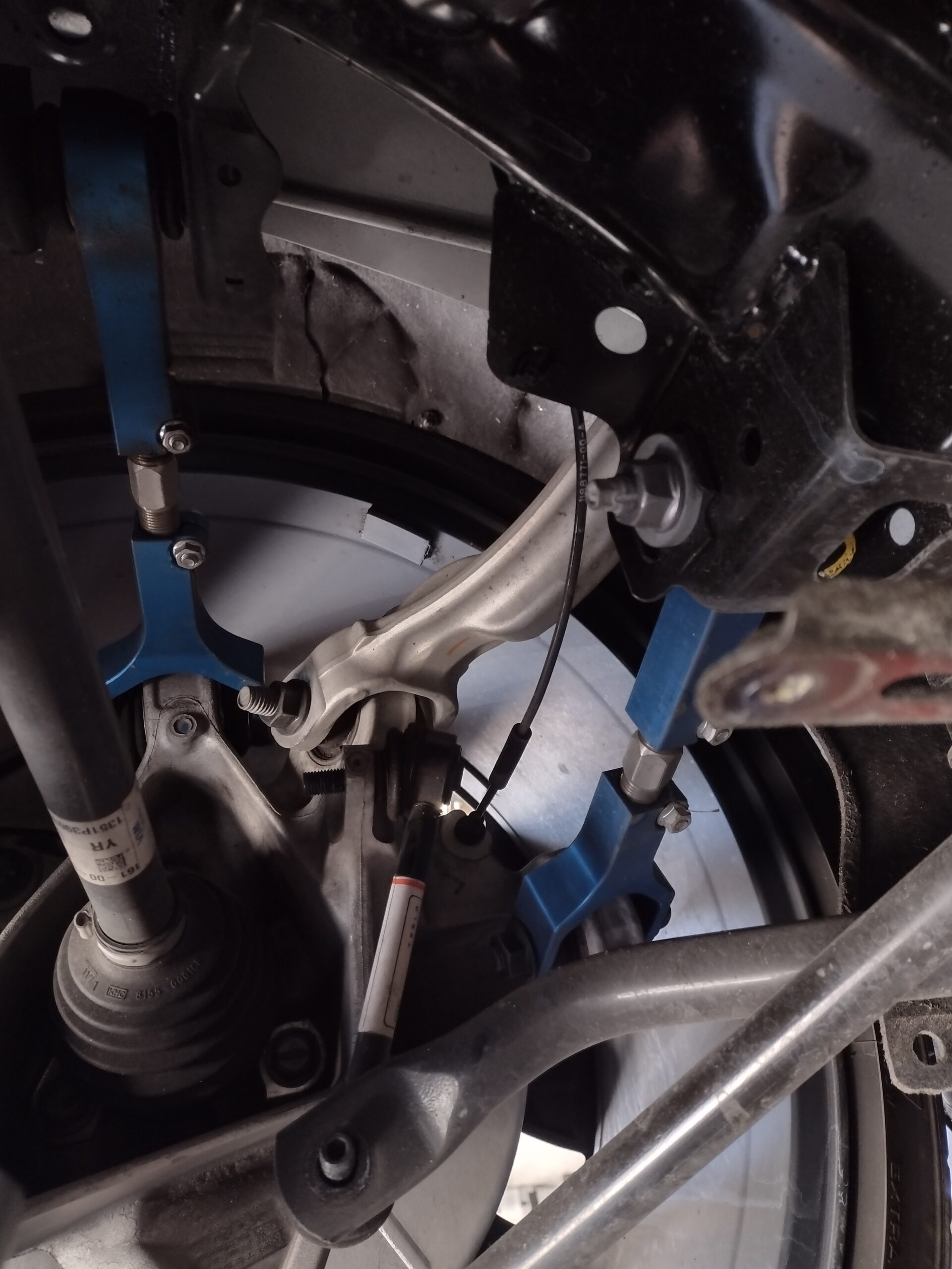
With the factory spindles in place, we prepare to mount the new Wilwood six piston calipers and multi-piece cross drilled rotors and bearing hub. The factory disc brake caliper mounted directly to the spindle and some of the casting is going to interfere with the new components and must be cut away. We measured and scribed cut lines, double checked, and then cut away the casting. After the rough cuts, a grinder we used to smooth and contour the spindle in preparation for mounting the new adapter brackets that support the Wilwood calipers.
Next we touched up the paint on the spindles and installed the mounts, bearing hubs, multi-piece rotors (there are a lot of bolts to put them together!) and the calipers. Here is a view from the backside showing the adapter brackets and caliper mounts.
With the front suspension and brake components installed, we move to the rear to build the rear axles, install the 4 link subframe mounts and subframe connectors. We will return to build out the steering including a new quick ratio steering box, upgraded sway bars and all new brake lines front to back in chapter 3.
Previously, we removed and cleaned the rear end housing and axle tubes of all grease and rust and painted the assembly. We removed the factory drum brake assemblies and noted that the car had a 3.07 / 3.08 rear gear ratio and an open differential carrier. Neither of these are particularly good for a performance build, so new 3.42 gears and a true track positraction unit were sourced. When we pulled the axles and inspected them, we found some pitting and an odd wear pattern where the wheel bearing rides on the right side axle suggesting that it was out of round or perhaps slightly bent. Along with the new gears, positraction carrier and carrier and pinion bearings, it made sense to upgrade the axles and install fresh wheel / axle bearings and seals.
To prepare for the rear end and suspension install, we removed and discarded the rear shocks and leaf springs. The front leaf spring mounts will be re-used to they were cleaned, stripped of rust and repainted. The pockets were cleaned, painted and new hardware was sourced. Subframe connectors were installed. The subframe connectors will make the car more rigid and better able to handle the increased loads that the new suspension and powertrain will deliver. Additionally, as this is a T-top car, the body benefits from the extra bracing. The subframe connectors install between the spring mounts and the body, and slide into the front subframe and are secured by the new body bolts and bushings previously installed there. We strengthened this further by welding the connectors to the front and rear subframe.
The Ride Tech 4 link system includes a new tubular subframe that bolts into the existing rear subframe to provide mounts for the upper links and the coilover upper mounts. We bolted and welded this assembly in place previously and took the opportunity to remove the fuel tank, seam seal and undercoat the bottom of the body in this area. The lower links connect to the lower mounts bolted to the leaf spring perches on the axle tube and connect to the forward leaf spring mounting perches. A jig is used to align the upper mounts on the subframe to mounting ears that must be welded to the top of the axle tube. We tack welded these in place for now and will fully seam weld and paint them after the car is on the alignment rack and pinion angle can be confirmed along with proper alignment of the rear axle. Since the 4 links are adjustable, the rear end can be properly centered and squarely aligned to the car. This is will result in a more accurate alignment than can otherwise be achieved with a leaf spring solid axle chassis.
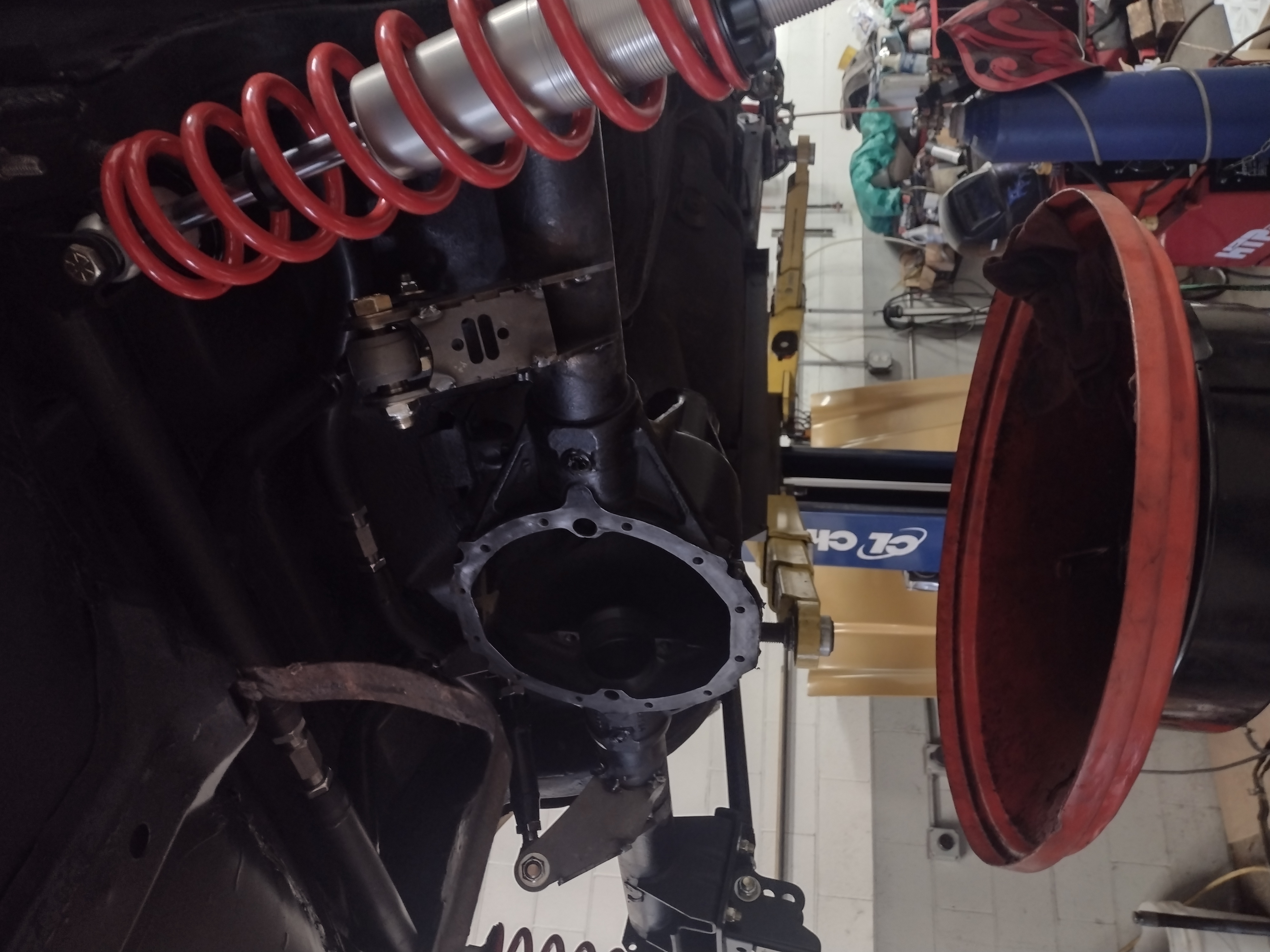
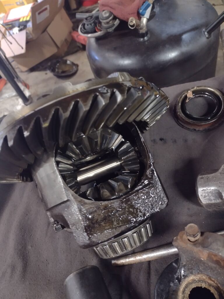
Here, the rear end is installed and the axles, gears carrier and bearings have been removed. The old differential with open carrier and spider gears is shown. The new 3.42 gear paired with the new 6 speed transmission should provide for quicker acceleration.
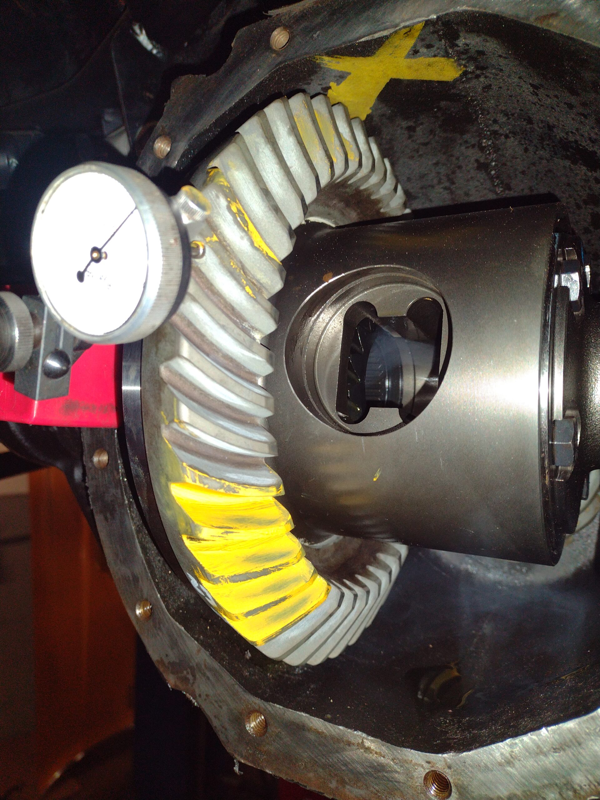
The new gears are assembled to the the true track posi-traction carrier, bearings pressed on to the carrier and the pinion gear and all fitted to the housing. Yellow marking compound is painted on sections of the gear teeth and dial gauge is fitted to check for backlash as shims are set. The marking compound shows the gear mesh pattern as adjustments are made and the setup finalized.
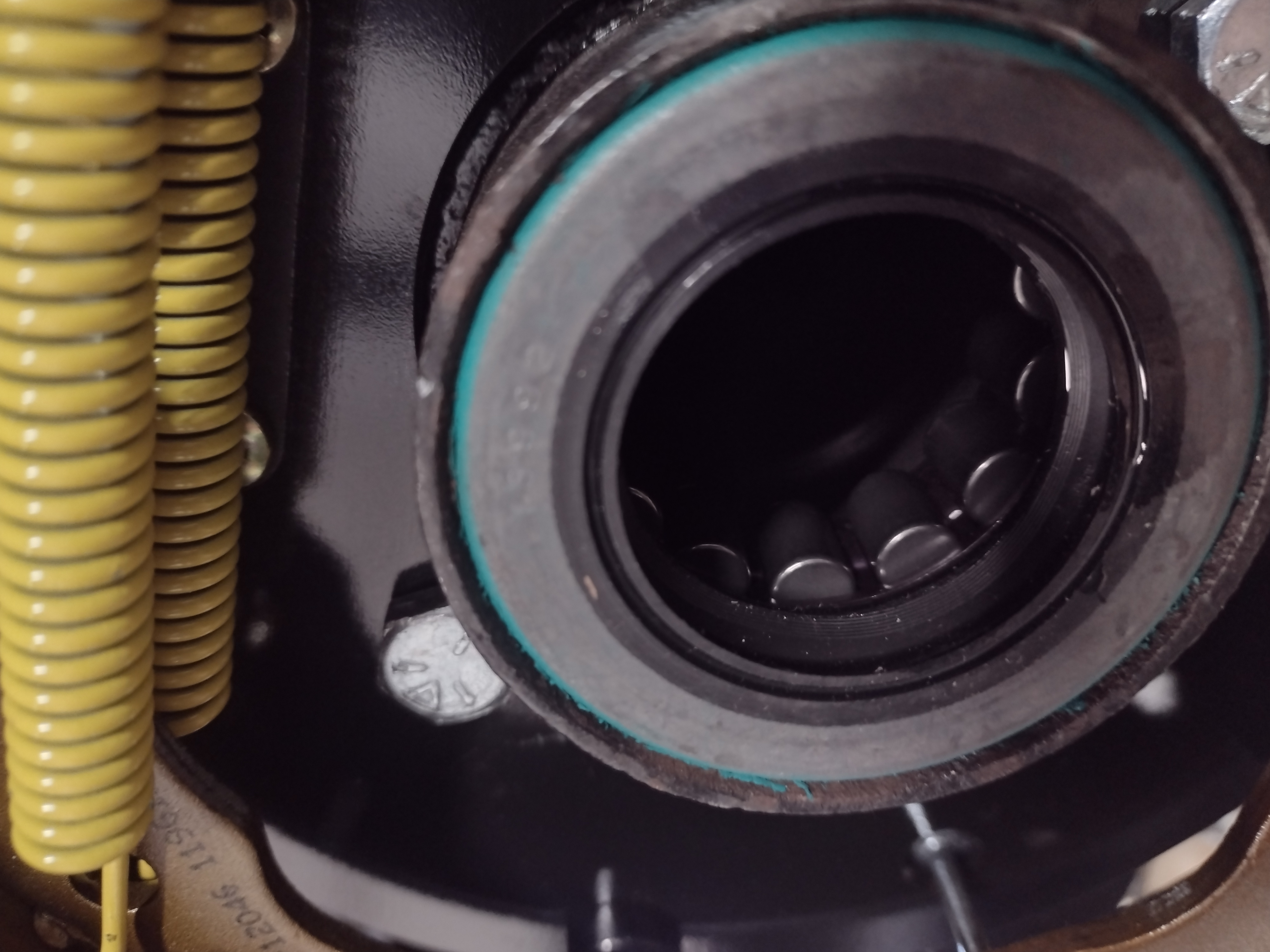
New wheel bearings and seals are installed along with new backing plates and the drum parking brake that will reside inside the rotor hat. The setup of the calipers was very time consuming and iterative as there are 3 bolts for each caliper to mounting plate and each must be shimmed with a combination of washers to ensure that the caliper is centered to the rotor and completely parallel. If not properly set up, the brake pads will not wear squarely.
The new Yukon gear axles are installed. These shipped with two stud patterns - the pressed in 7/16" studs shown will be knocked out in favor of the screw in 1/2" studs that match the front hubs.
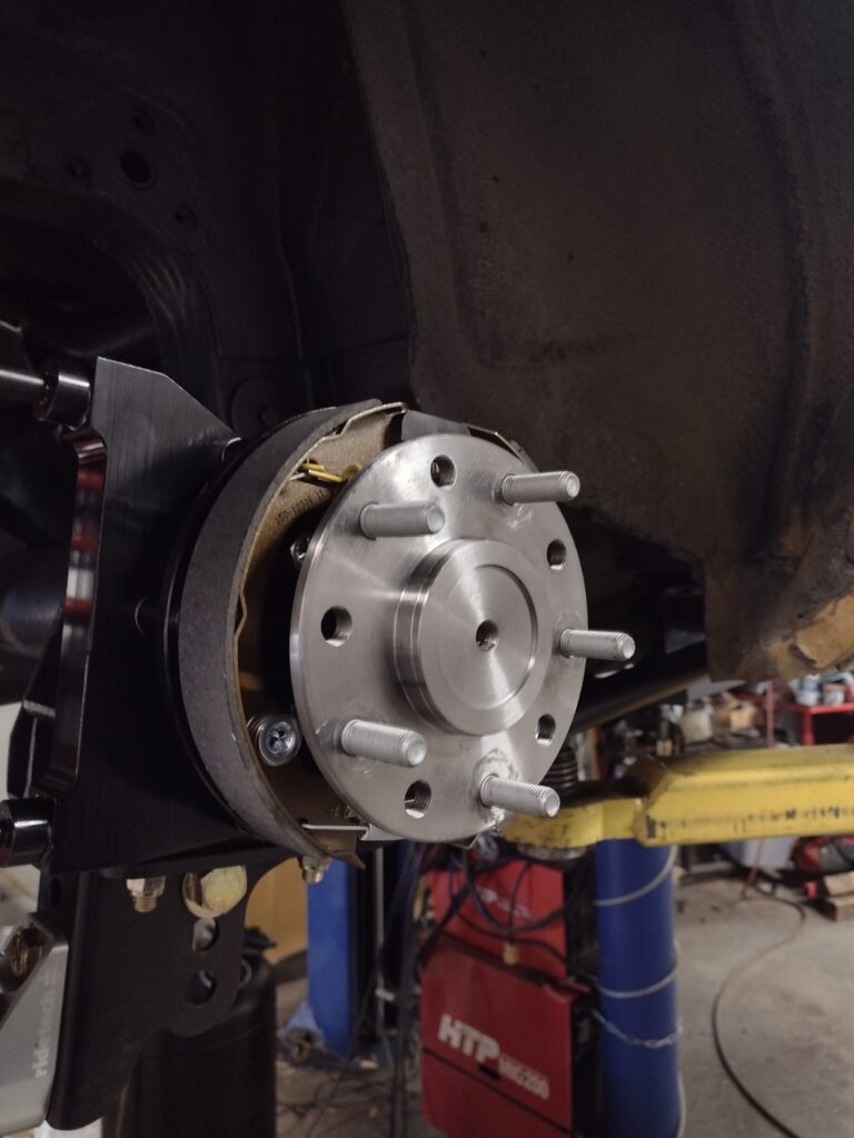
After a number of shim iterations on both sides, the calipers are properly aligned to the rotors and the completed assembly is installed. This was particularly time consuming because one of the three bolts was inaccessible due to the lower spring mount and so the 4 bolts that secure the entire assembly inside the brake shoe area behind the axle had to be removed to allow the entire assembly to rotate 90 degrees clockwise to adjust the shims and reinstall the bolts, the rotating back and re-installing the 4 bolts, with repeated measurements at 3 points to check alignment with the rotor. This can take a couple of hours of adjustment after all the preliminary assembly has already been completed (building the multi-piece rotors), and is a reason why this particular rear brake setup is not the same as bolting on a set of pads and rotors in your driveway on a Saturday afternoon.
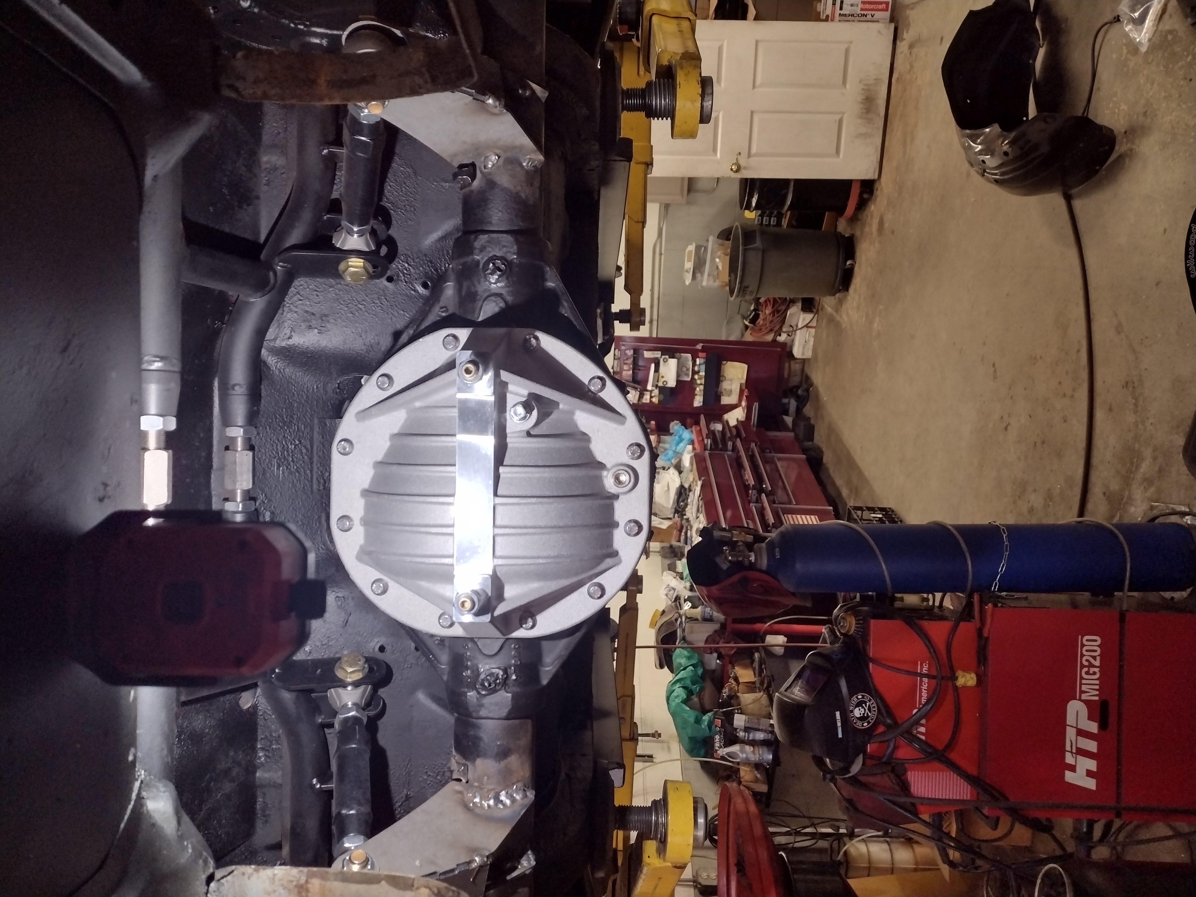
Here the rear is assembled and ready to be filled with oil once we have verified the placement of the upper mounts on the alignment machine and fully seam welded and repainted these areas. We fitted a new aluminum rear axle cover that includes fins to help cool the differential oil and a rear bearing cap brace to strengthen the diff assembly.
In Part 3, we will run all new brake lines, connect the emergency brake system, install a new quick ratio steering box (3 turns lock to lock), fit all new steering components and install some beefy anti-sway bars along with new wheels and tires to get us ready to roll onto the alignment rack.
Tesla Suspension Upgrades
We have performed a number of suspension upgrades for Tesla owners who want improved handling and ride quality. Frequently, we hear that the factory ride is too stiff, and that early tire wear, especially on rear tires, can be a concern.

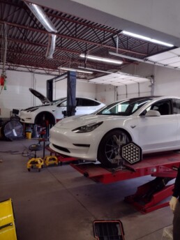
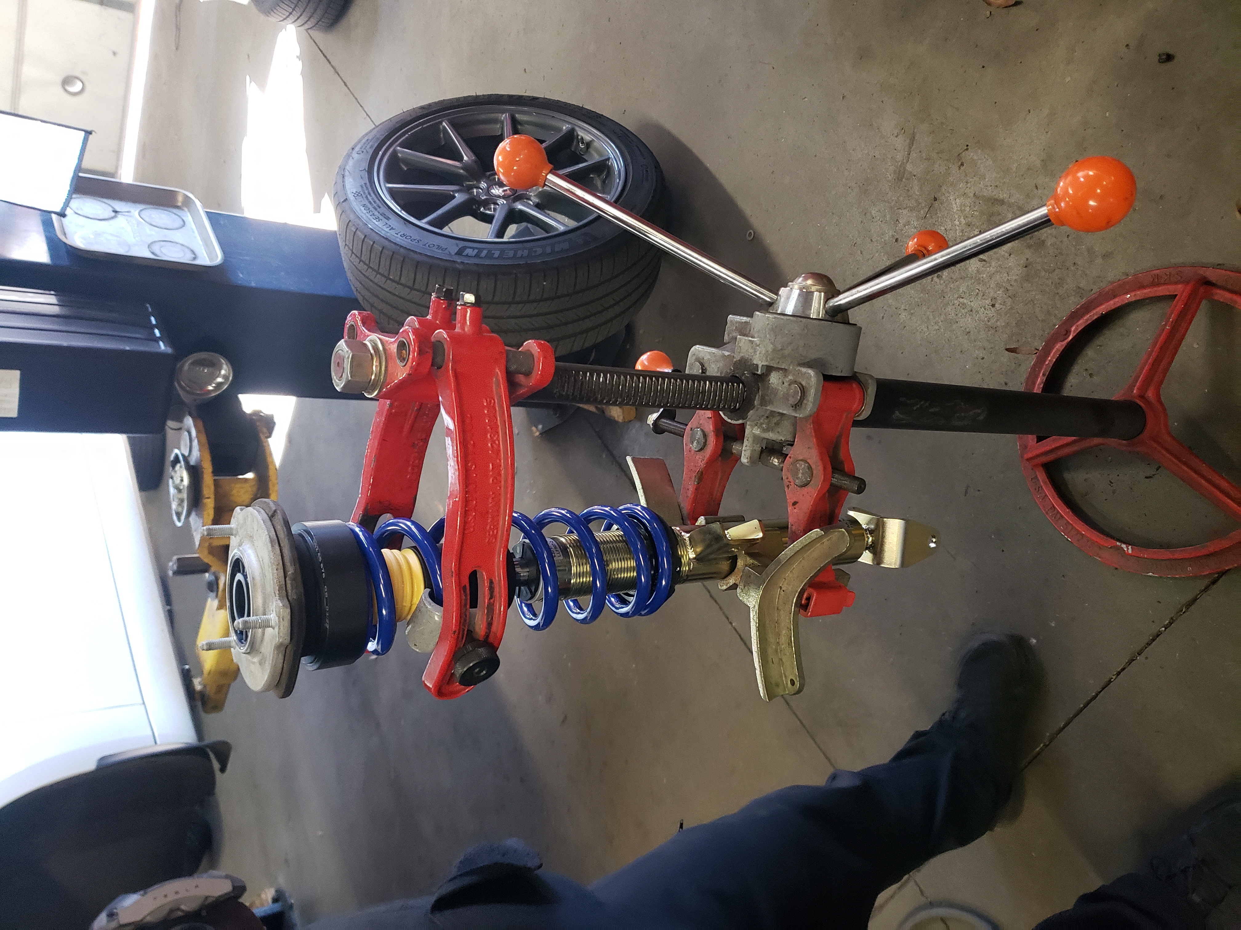
Here we have two Teslas in the shop and are aligning a Model Y following ride height adjustment and installation of Mountain Pass coilovers and adjustable rear camber arms in place of lowering springs and rear camber arms from unplugged.
The Mountain Pass components are high quality and we highly recommend them as a proven and durable solution. There are cheaper rear camber arms available, but often the adjusters are difficult to access on the vehicle due to the design. These arms are high quality, look great and are a pleasure to install and adjust.
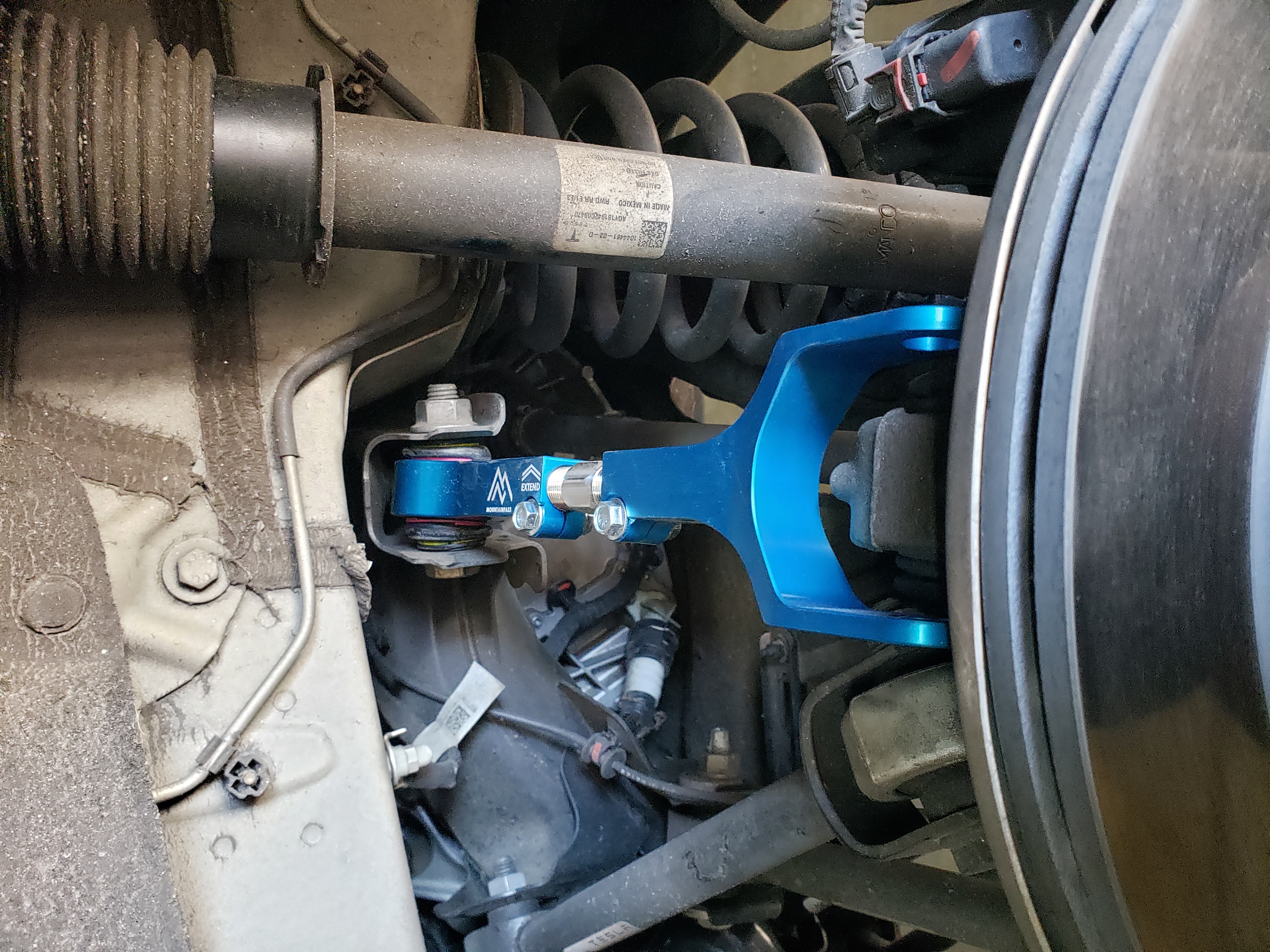
Here is another example Tesla where we installed Mountain Pass adjustable rear Camber and Toe arms. These, paired with the front adjustable upper control arm option allow alignment values to be dialed in for those who want to further optimize handling and tire life.
Many owners opt to lower their vehicles and lowering springs offer some initial economic advantage over coil overs in simplicity of install and no additional labor to set ride height. However, as they settle, there is no option to adjust the ride height to be even side to side and front to rear, or to further adjust for owner preference.
Here, we remove lowering springs previously installed at another shop in favor of coil overs. The owner of the other Tesla shown above wanted to improve ride quality and had us install Tien struts with adjustable valving so he could tune the rebound on front and rear of the vehicle to his preferred ride quality. Adjustable camber arms were also installed in this case as lowering the vehicle tends to increase negative camber which can lead to tire wear on the inside edges of the rear tires. Setting rear toe closer to zero can help offset this and reduce tire wear, but the adjustable camber arms provide greater adjustability.
If you want to improve the ride, handling, and tire life on your Tesla, give us a call! We have performed installs on Polestar and other EV's as well.
Project 1970 Camaro SS - Part 1
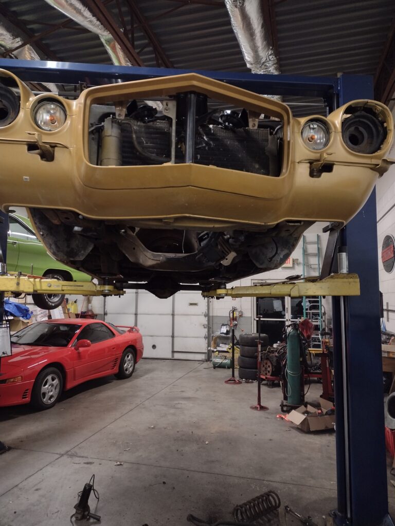
Our customer wanted to restore this 1970 Camaro SS that has been in storage for about 20 years. The car is interesting in that it has the highly desired split bumper front end typically associated with Z28 cars of the year and has the heavy duty 12 bolt rear end and rear sway bar, but currently lacks a positraction carrier. The powertrain was a small block 350 backed by TH350 automatic with factory floor shifter. Someone added T tops somewhere along the way and they are well done.
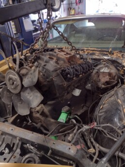
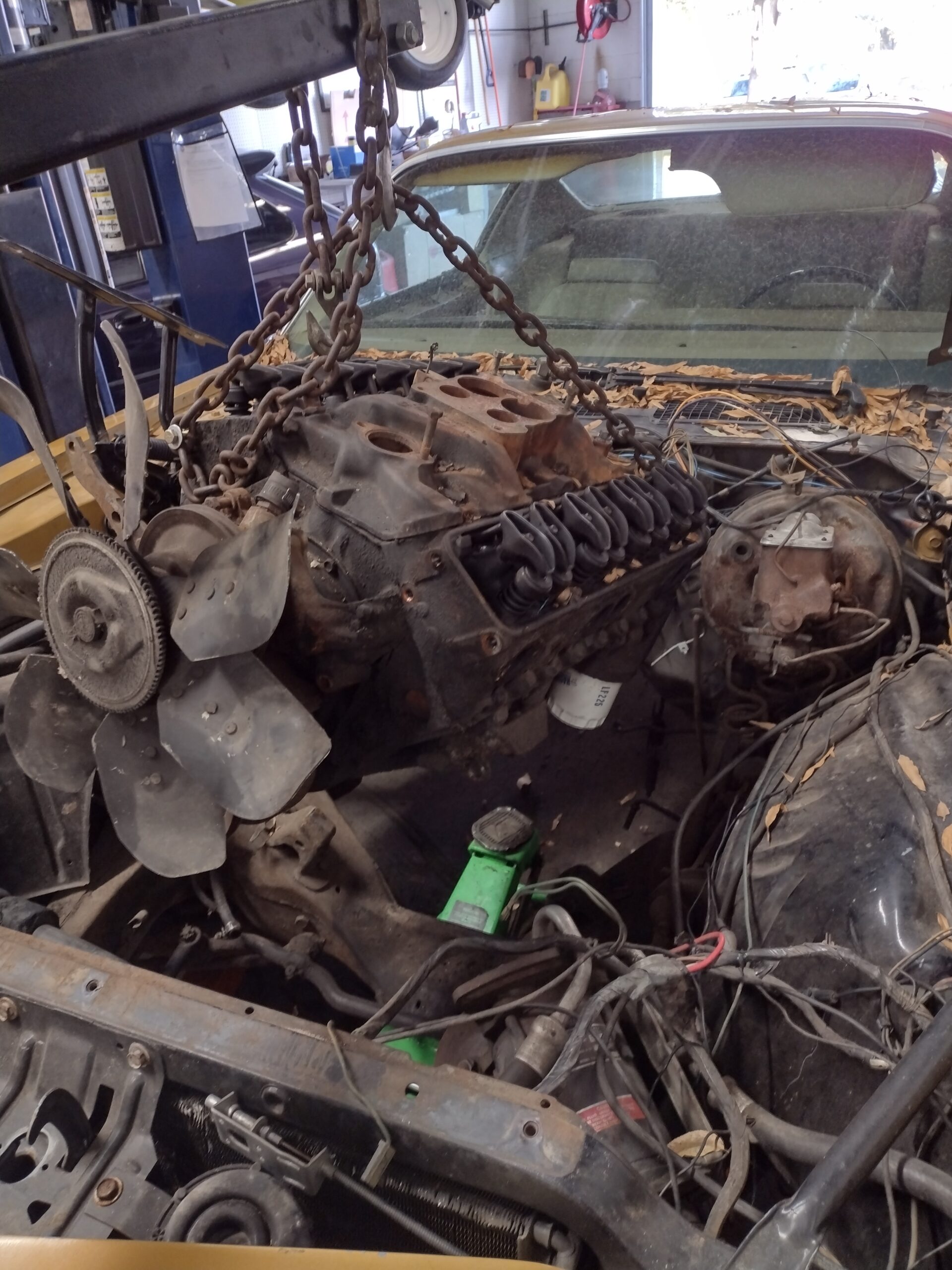
We began work stripping lights, bumpers and much of the interior, removing the hood and pulling transmission first, and then the engine.
The wiring harness had been cut up and the owner has a new wiring kit we will install later in the project. The front suspension and steering were removed, along with the fender liners.
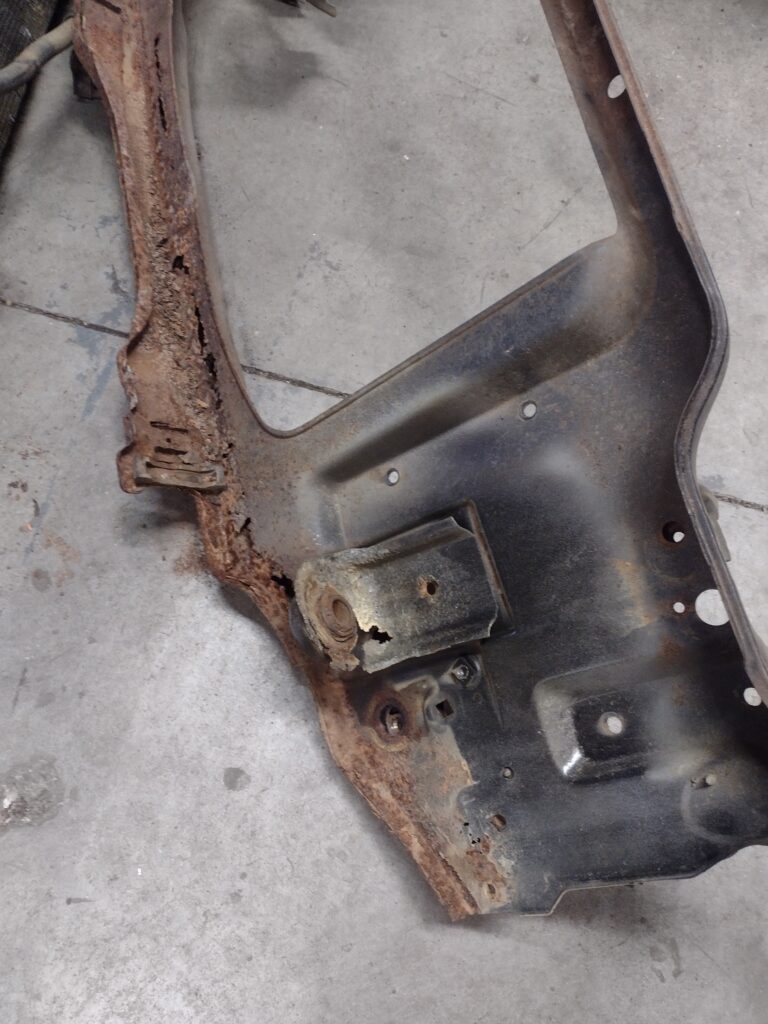
The radiator support was pretty rusty, so it seemed like a good opportunity to replace it with a high quality reproduction.
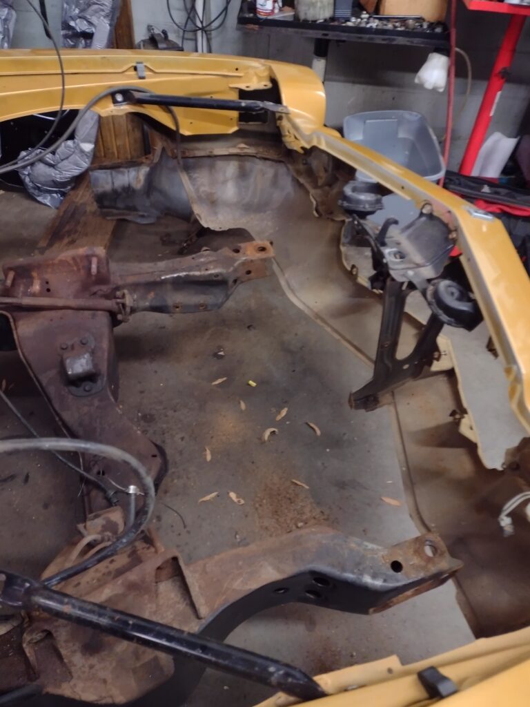
While we are waiting on the new radiator support we took the opportunity to clean and strip the front subframe and paint it with POR-15 to provide a good clean canvass for installation of the new suspension components.
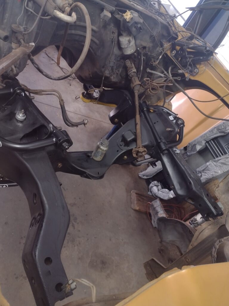
Next we install the upper and lower control arms, assemble and install the coilovers setting the initial preload. The control arms fit well and work with the factory spindles which were cleaned and painted as well. The upper ball joint is designed to work with other spindles, and when used with the stock spindles, a significant portion of the taper extends above the spindle. We sleeved this in a cut section of hose.
In our next installment, we will install the spindles and make some modifications to the spindles to support the new Wilwood brake system. The section of the spindle used to mount the original GM caliper must be cut away to make room for the adapter brackets.
The rear is similarly in progress with the factory leaf springs, shackles and shocks removed and the rear end and fuel tank removed from the car. This affords us an opportunity to clean and paint the under car area of the rear, remove the factory sway bar and bump stop mounts and prepare to install the subframe support that will provide the mounting points for the rear coil overs and upper control arms of the four link system.
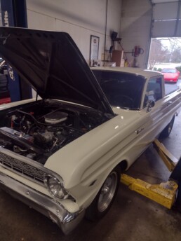
Ford Falcon Ranchero Steering Box Upgrade
We recently had the opportunity to install a quicker 16:1 ratio manual steering box in place of the factory 20:1 ratio steering box in a 1964 Falcon Ranchero to improve steering response. Power steering equipped models and high performance Mustang models came with the faster 16:1 ratio from the factory. Because the steering box was manual, the faster ratio would also increase steering effort. To offset this, our customer selected and provided a roller bearing idler arm.

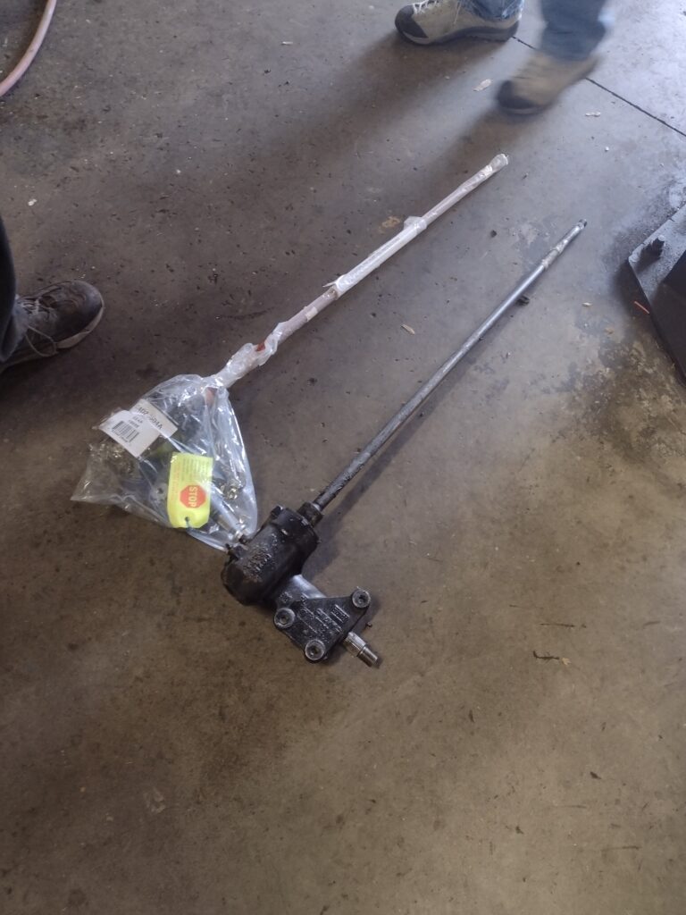
The steering box in this vehicle is more challenging to replace because the steering shaft is rigid and is integrated with the steering box. This makes removal and installation more complex, requiring disassembly of the steering column. Here we can see the old and new steering boxes.
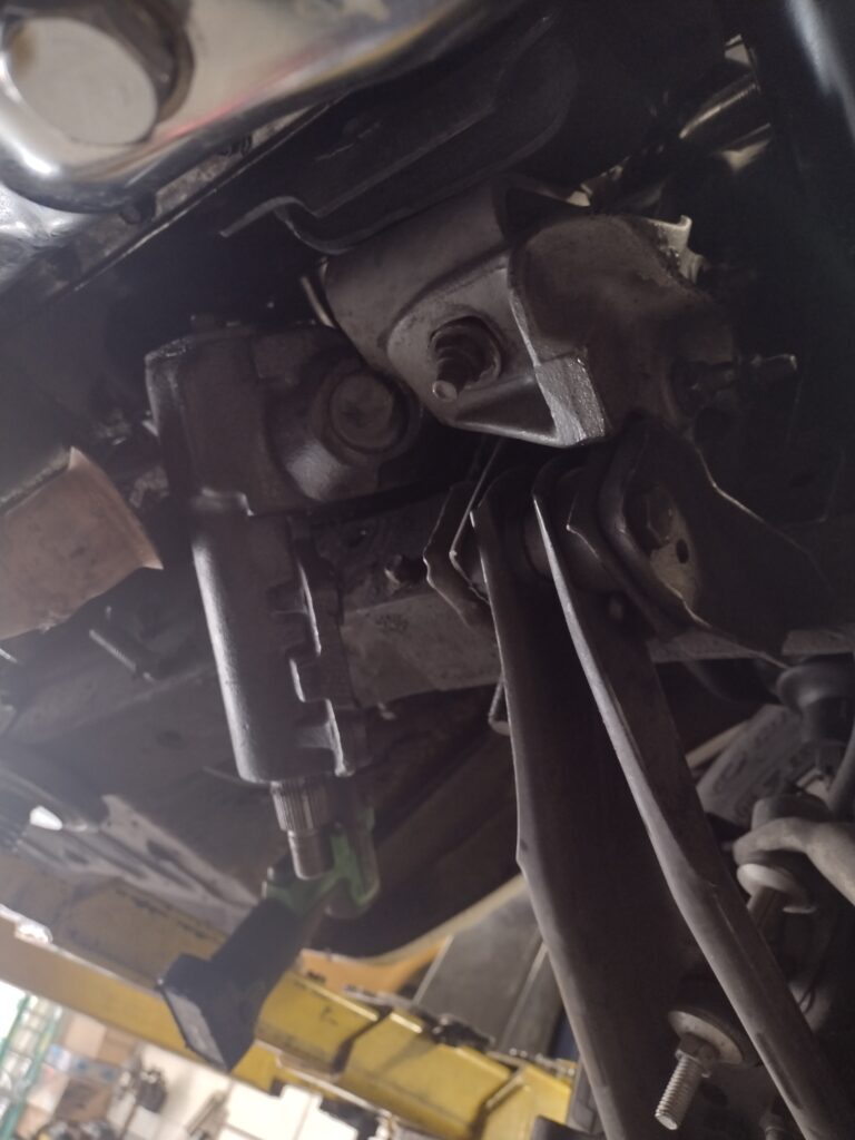
The 1964 Ranchero was available with several six cylinder engine options and one 260 cubic V8. This particular car had a 351W swapped in, and the shock towers had been sectioned and rewelded to provide room for the V8 by a previous owner. Once the steering box was unbolted from the frame, and the steering column disassembled and removed from its mount so the box could pivot away from the frame, we found that the exhaust manifold and motor mount on the driver side prevented the box from being removed, so the engine was supported, the exhaust pipes, manifold, and engine mount were removed.
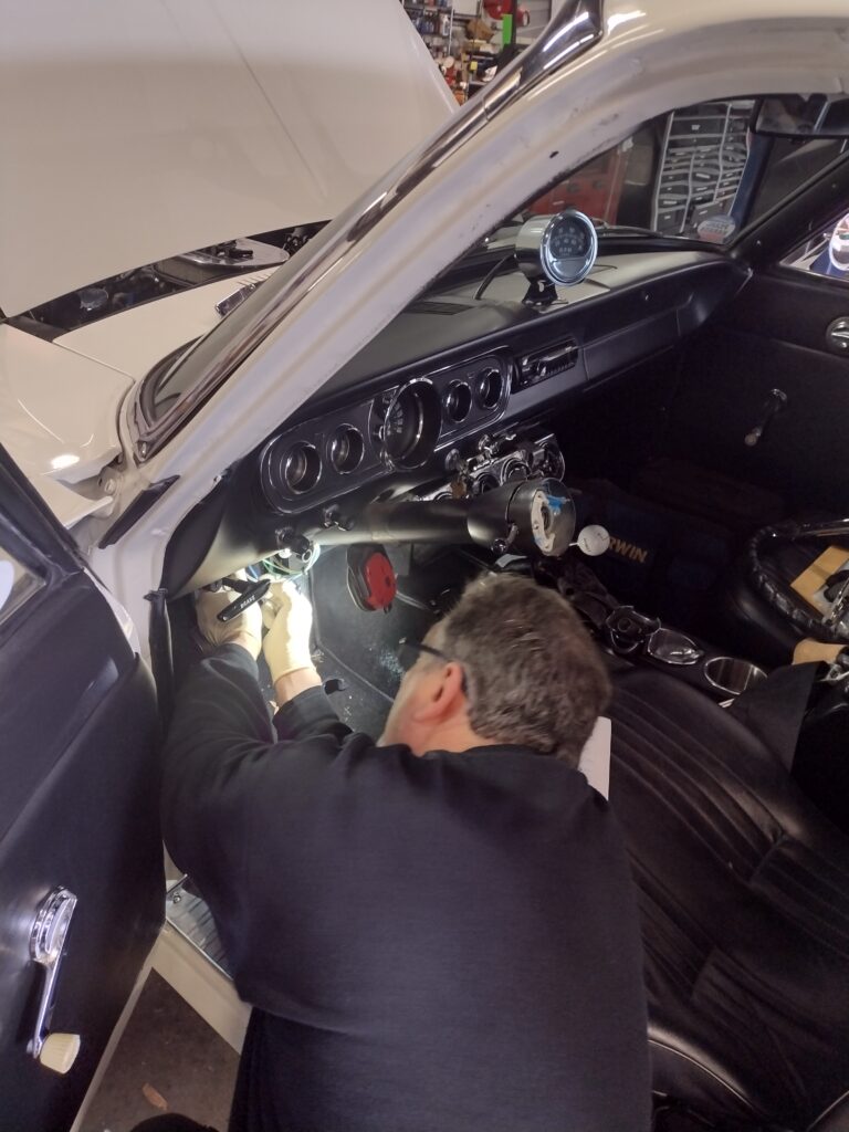
With the pitman arm also disconnected, the steering box was removed and replaced, the idler arm swapped, and then everything was reassembled. While the steering column was apart, we had an opportunity to address another issue identified by the owner, the turn signals did not turn off as expected when the wheel was straightened following a turn. There is a plastic cam assembly on the left side of the column in alignment with the turn signal lever and there area pair of prongs attached to a ring that are supposed to engage them. These were found to have been installed to the right, 180 degrees from where they needed to be, during some prior service work in the column. The collar supporting the prongs was pulled and correctly re-indexed and the column and steering wheel re-assembled.
Following reassembly, the Ranchero was aligned setting caster and camber, and resetting toe. We hope the improved steering responsiveness adds to the pleasure of driving this 351W powered, 4 speed manual shifted classic Ford. The amazing paint and American classic wheels make this a real head turner!

Engine Swap Plymouth Scamp
Swapping in a built 360 Magnum
Tom wanted to build a classic American Muscle Car, and after kicking some tires, found a 1973 Plymouth Scamp with a 318 V8 (the only V8 offered for the car in that year). Some previous restoration work had been undertaken and the body was straight and sound, so it seemed like a good canvas for his future vision.
We've worked previously with Tom on this project to sort out the steering and front suspension and to upgrade the car in other ways including the addition of a digital dash. During those visits, we worked on drivability and tracking down the cause of a persistent miss. It turned out that the tired 318 motor had a dead #8 cylinder, only making 60 lbs of compression.
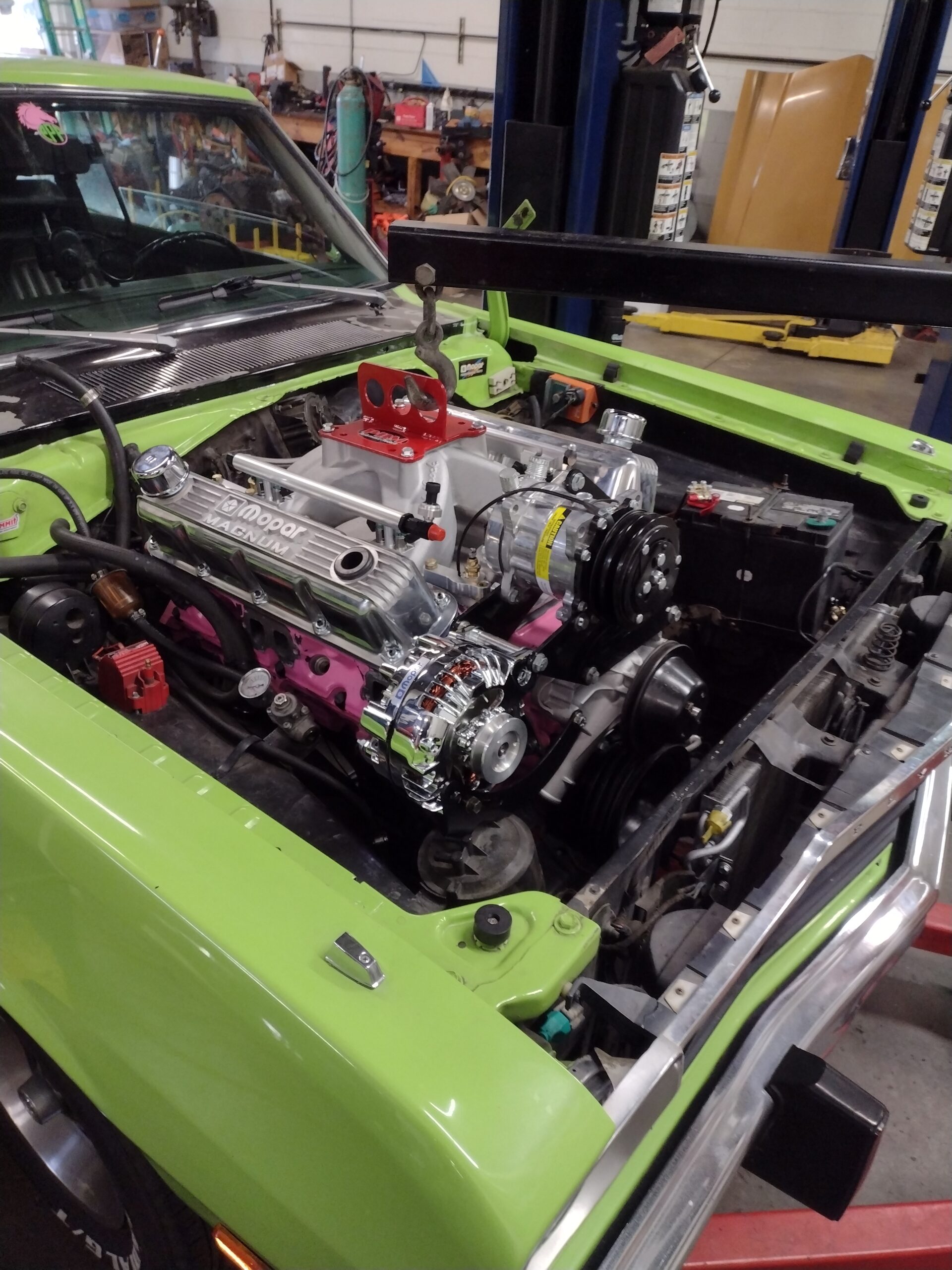
Tom took the news in stride, and used it to catalyze the next phase of his build starting with a freshly machined 360 Magnum block fitted with roller cam, roller rockers, .030 over hypereutectic pistons. A set of ceramic coated headers, new 2.5" dual exhaust pipes and turbo mufflers deliver the nostalgic exhaust note, while an Edelbrock ProFlo-4 intake, throttle body and computer modernized the induction to deliver power and modern drivability. The Magnum heads and intake required a small amount of machine work to adapt the bolt locations for the intake.

The Magnum 360 was dimensionally the same as the LA 318 it replaced with only some slight modifications such as a spacer on the driver side motor mount, modification to the lower alternator bracket (section, reweld, build up) to fit the bolt location on the Magnum head (about 1/2" variance) and elongation of one of the 4 torque converter to flexplate bolt holes required to bolt it in.
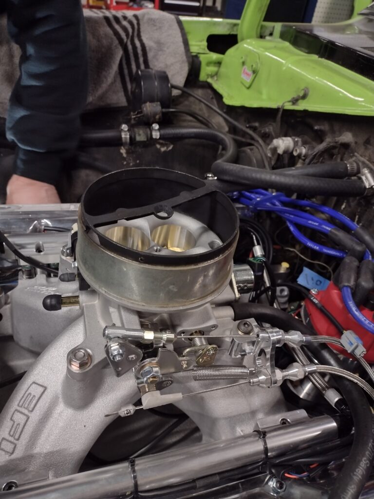
The Edelbrock FI system uses 35lb / hr injectors and a 58 PSI Holley in tank pump (internally regulated) and sender combination that was a direct bolt in replacing the stock sender and fuel suction line. This system combination allows operation without a return line. We used a compression to AN fitting to connect a matching AN6 line to the fuel rail for a neat and finished appearance. Lokar cables were used for the trans kickdown and throttle. A 1" spacer under the air cleaner was required to provide clearance for the throttle linkage and allowed the hood to close with the open element 14" air cleaner. Shown above was a 2" spacer used for test fitting. This fuel system supports up to 550 hp.
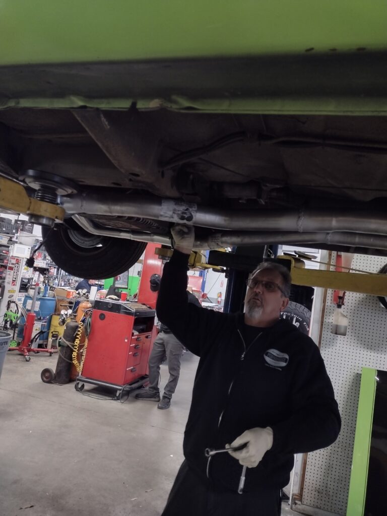
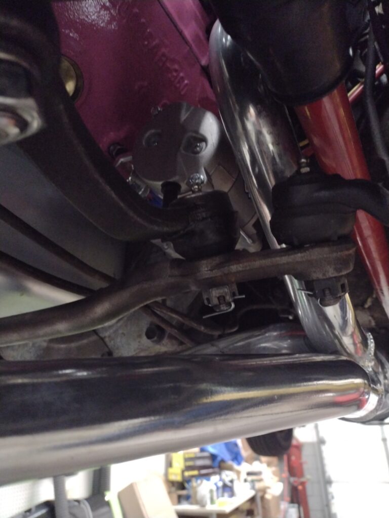
The headers were a tight fit, especially on the driver side where they needed to be fit in the car before the engine settled into place. There wasn't much room to work in some of the header bolts and so 12 point bolt heads are a big help. Once the headers were in, we fitting the dual exhaust kit and mufflers with some modification needed on the passenger side to line up with the relief in the cross member. The kit came with a copious number of muffler clamps which we used while test fitting the system completely, then tack welded, remove the clamps and seam welded all the joints except for tail pipe connection to the mufflers off the car to ensure leak free connections. The single clamp at the muffler exists provide a hanger attachment point, and allow the tailpipes to be removed in case future services necessitate removal of the exhaust. (We know a rear end swap and manual trans conversion are in the plan)
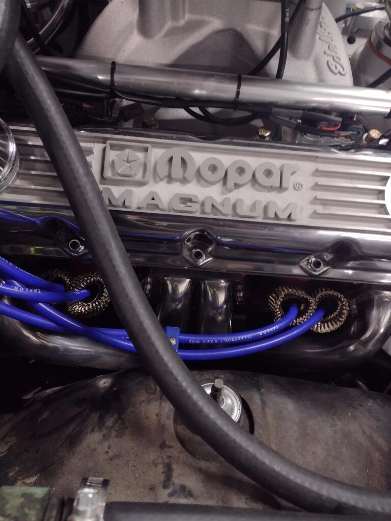
The steering linkage passed through the driver side header pipes adding an additional consideration to the install, and two of the plug wires are in close contact with the primary pipes on the driver side, so we added heat sleeves to all the plug wires.
After ensuring an oil prime, timing was set based on the balancer markings and validation of TDC through #1 cylinder bore, we were ready to download the base tune and start the car. Edelbrock provides a free app and with a few simple questions about engine displacement, Cam selection (one of three ranges of specs), injector size, fuel pump PSI (43 or 58) and whether naturally aspirated or super / turbocharged, a base tune is downloaded. The engine fired on the first go and ran at a fast idle. A setup wizard guided through setting a target idle RPM and adjusting the throttle stop so that the IAC had sufficient range to manage. Afterward, the system is self learning as one expects, and supports additional advanced tuning through the app.
Tom has an upgraded rear end ready to go and will be back with the Scamp for that install soon stay tuned!