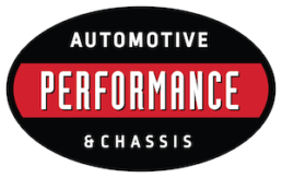
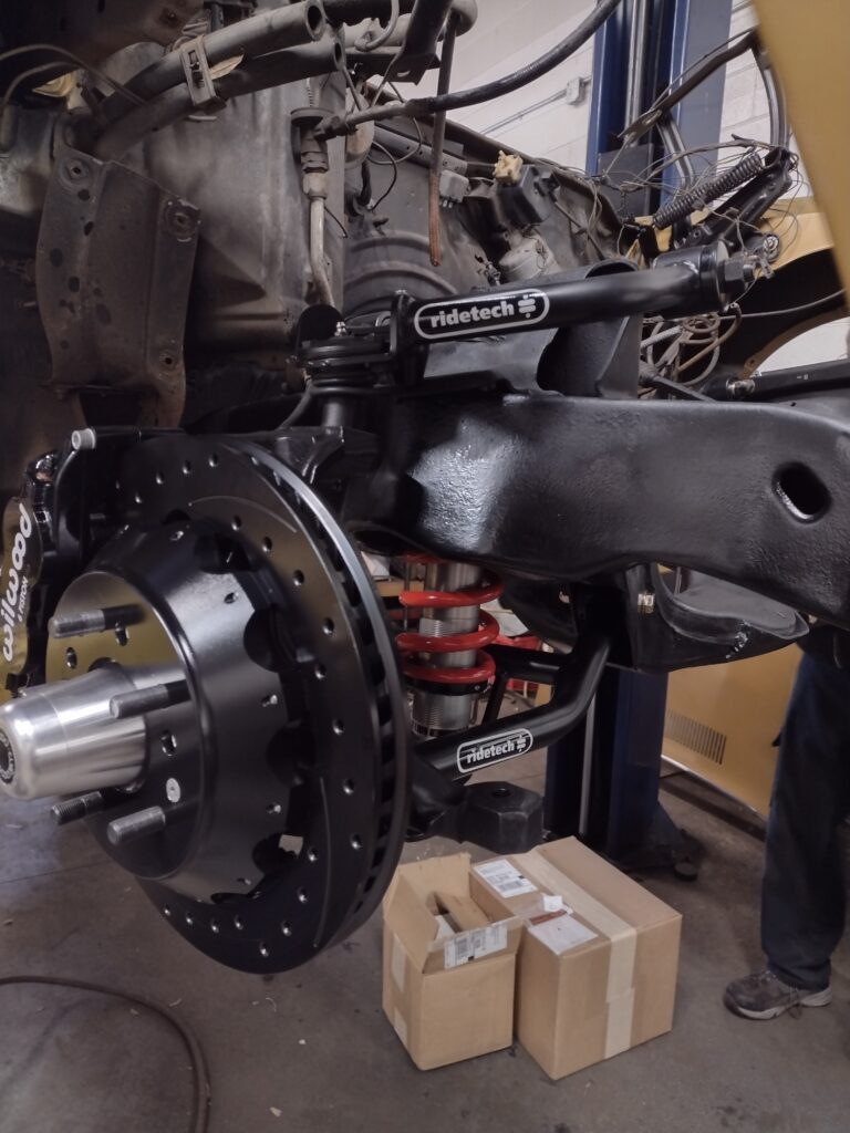
In Part 1 of this build story we removed the powertrain, exhaust system, front and rear steering and suspension, fender liners and radiator support, cleaned and painted the frame. Now, we are ready to install the new Ride Tech upper and lower control arms, coil overs, and get ready to mount our original spindles which have been thoroughly cleaned, rust removed, and repainted.
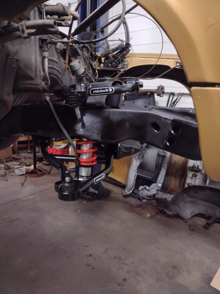
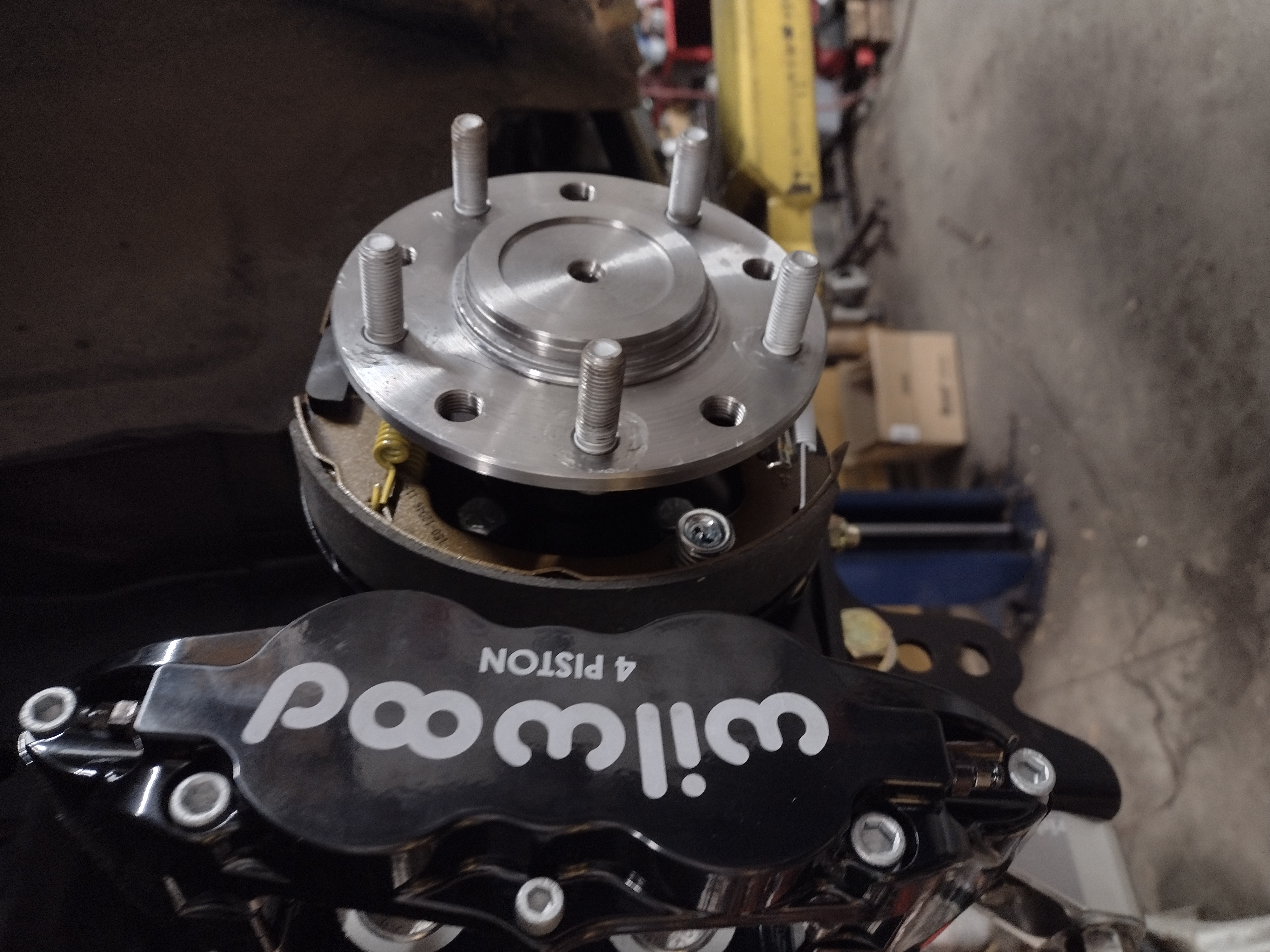
With the factory spindles in place, we prepare to mount the new Wilwood six piston calipers and multi-piece cross drilled rotors and bearing hub. The factory disc brake caliper mounted directly to the spindle and some of the casting is going to interfere with the new components and must be cut away. We measured and scribed cut lines, double checked, and then cut away the casting. After the rough cuts, a grinder we used to smooth and contour the spindle in preparation for mounting the new adapter brackets that support the Wilwood calipers.
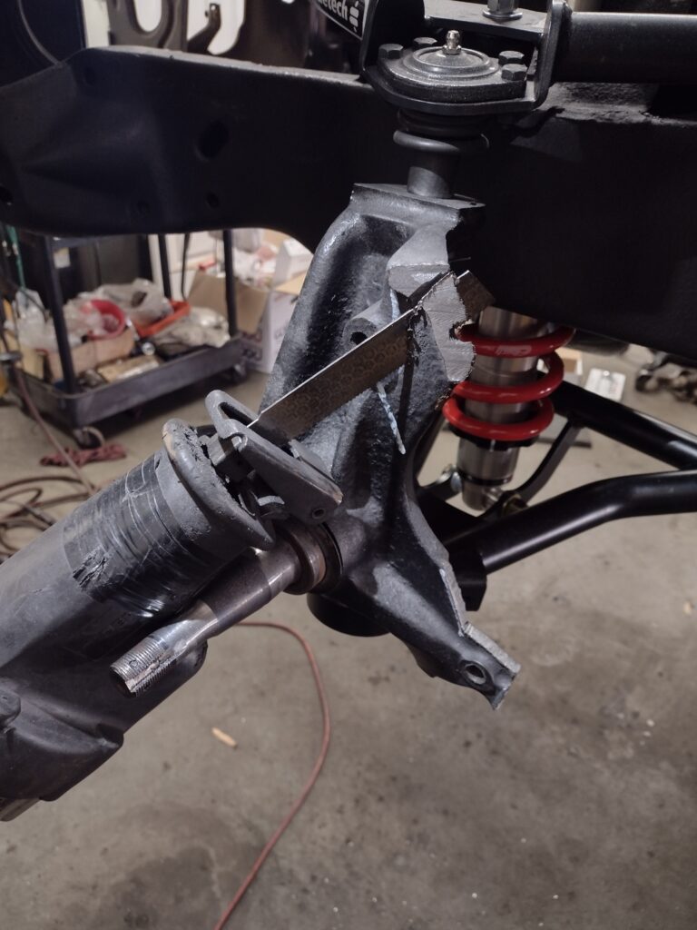
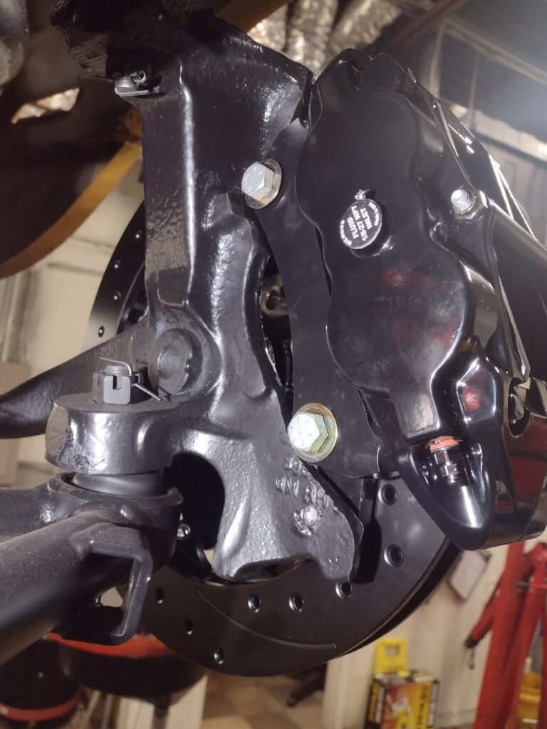
Next we touched up the paint on the spindles and installed the mounts, bearing hubs, multi-piece rotors (there are a lot of bolts to put them together!) and the calipers. Here is a view from the backside showing the adapter brackets and caliper mounts.
With the front suspension and brake components installed, we move to the rear to build the rear axles, install the 4 link subframe mounts and subframe connectors. We will return to build out the steering including a new quick ratio steering box, upgraded sway bars and all new brake lines front to back in chapter 3.
Previously, we removed and cleaned the rear end housing and axle tubes of all grease and rust and painted the assembly. We removed the factory drum brake assemblies and noted that the car had a 3.07 / 3.08 rear gear ratio and an open differential carrier. Neither of these are particularly good for a performance build, so new 3.42 gears and a true track positraction unit were sourced. When we pulled the axles and inspected them, we found some pitting and an odd wear pattern where the wheel bearing rides on the right side axle suggesting that it was out of round or perhaps slightly bent. Along with the new gears, positraction carrier and carrier and pinion bearings, it made sense to upgrade the axles and install fresh wheel / axle bearings and seals.
To prepare for the rear end and suspension install, we removed and discarded the rear shocks and leaf springs. The front leaf spring mounts will be re-used to they were cleaned, stripped of rust and repainted. The pockets were cleaned, painted and new hardware was sourced. Subframe connectors were installed. The subframe connectors will make the car more rigid and better able to handle the increased loads that the new suspension and powertrain will deliver. Additionally, as this is a T-top car, the body benefits from the extra bracing. The subframe connectors install between the spring mounts and the body, and slide into the front subframe and are secured by the new body bolts and bushings previously installed there. We strengthened this further by welding the connectors to the front and rear subframe.
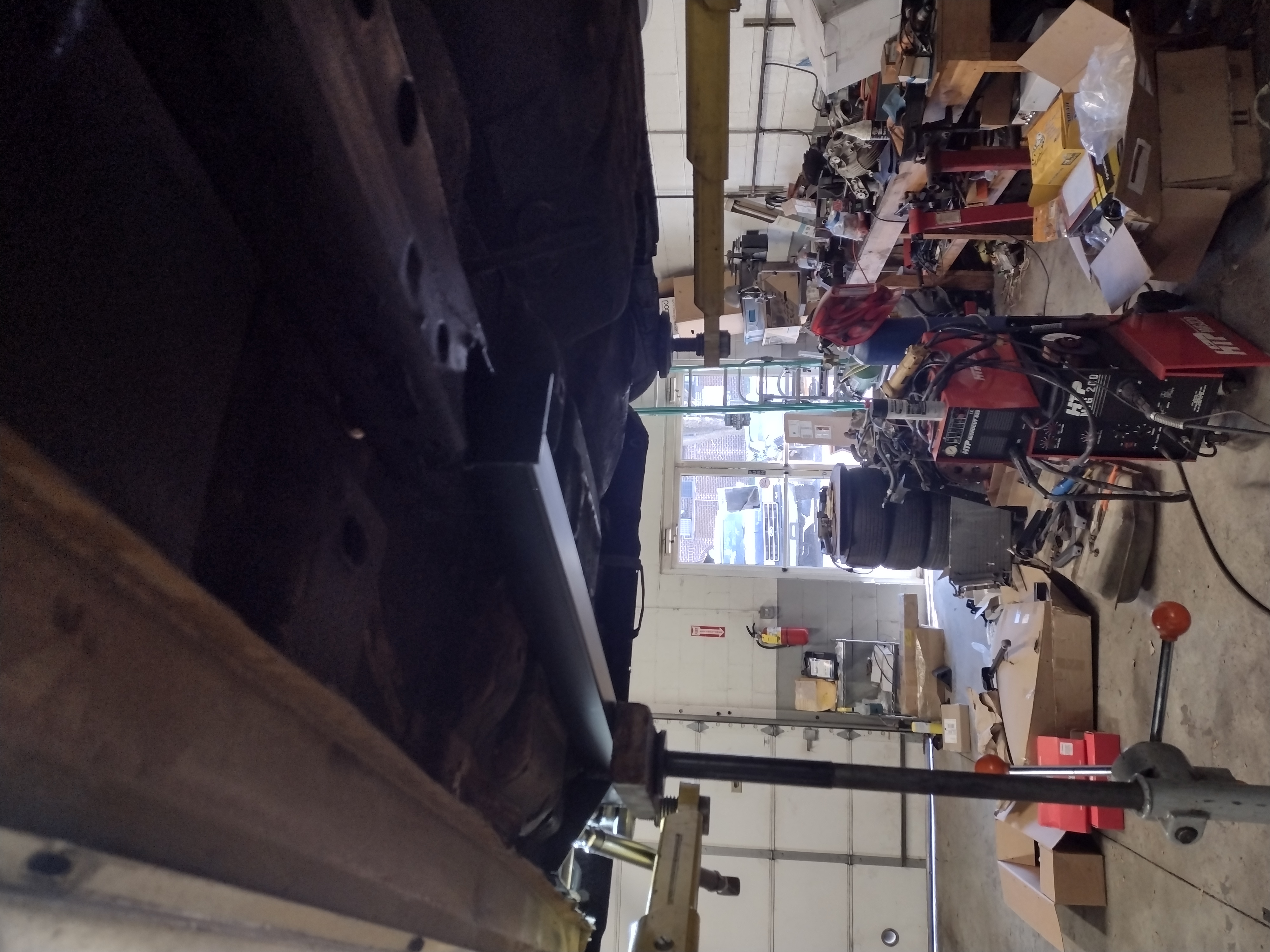
The Ride Tech 4 link system includes a new tubular subframe that bolts into the existing rear subframe to provide mounts for the upper links and the coilover upper mounts. We bolted and welded this assembly in place previously and took the opportunity to remove the fuel tank, seam seal and undercoat the bottom of the body in this area. The lower links connect to the lower mounts bolted to the leaf spring perches on the axle tube and connect to the forward leaf spring mounting perches. A jig is used to align the upper mounts on the subframe to mounting ears that must be welded to the top of the axle tube. We tack welded these in place for now and will fully seam weld and paint them after the car is on the alignment rack and pinion angle can be confirmed along with proper alignment of the rear axle. Since the 4 links are adjustable, the rear end can be properly centered and squarely aligned to the car. This is will result in a more accurate alignment than can otherwise be achieved with a leaf spring solid axle chassis.
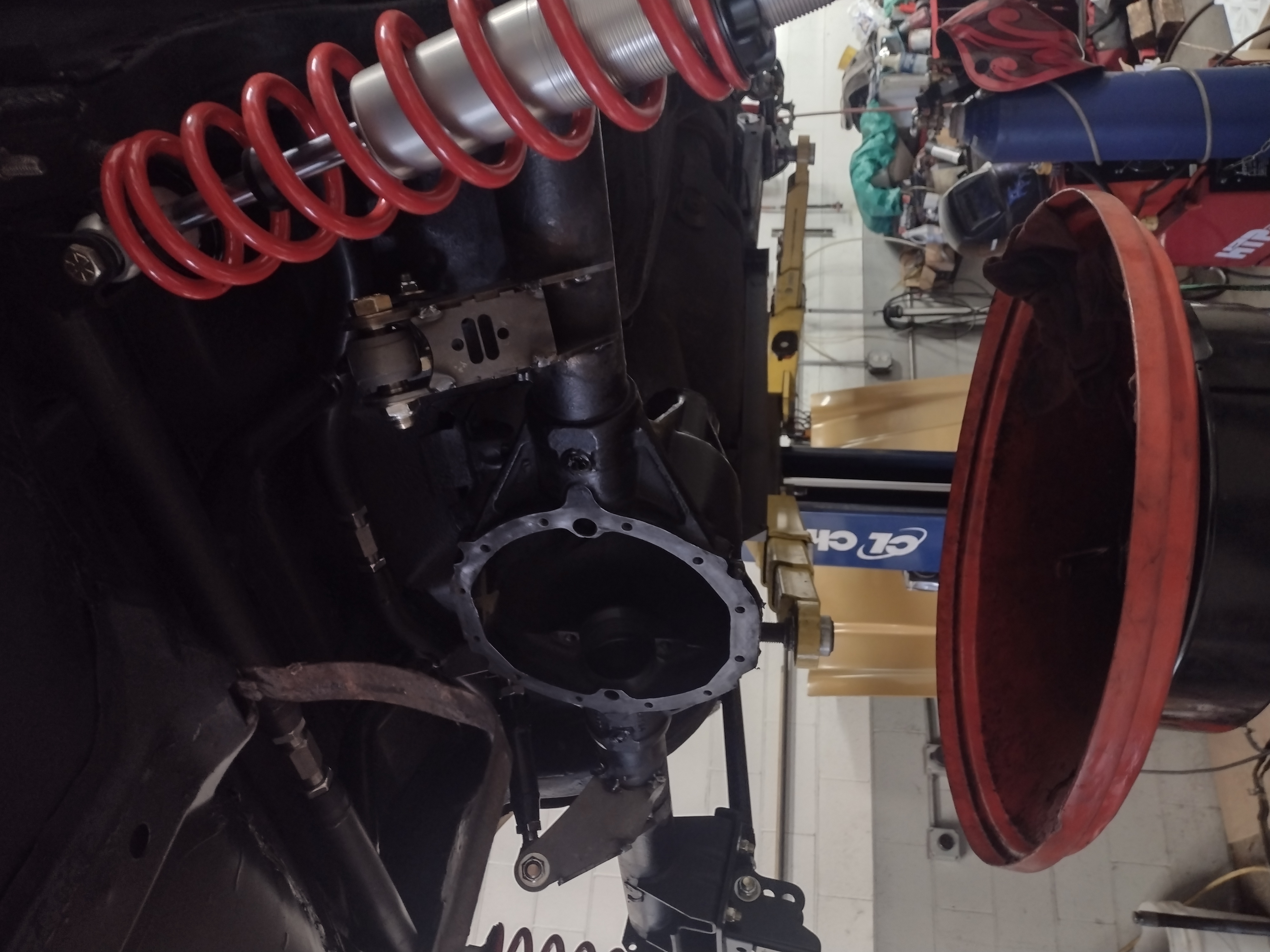
Here, the rear end is installed and the axles, gears carrier and bearings have been removed. The old differential with open carrier and spider gears is shown. The new 3.42 gear paired with the new 6 speed transmission should provide for quicker acceleration.
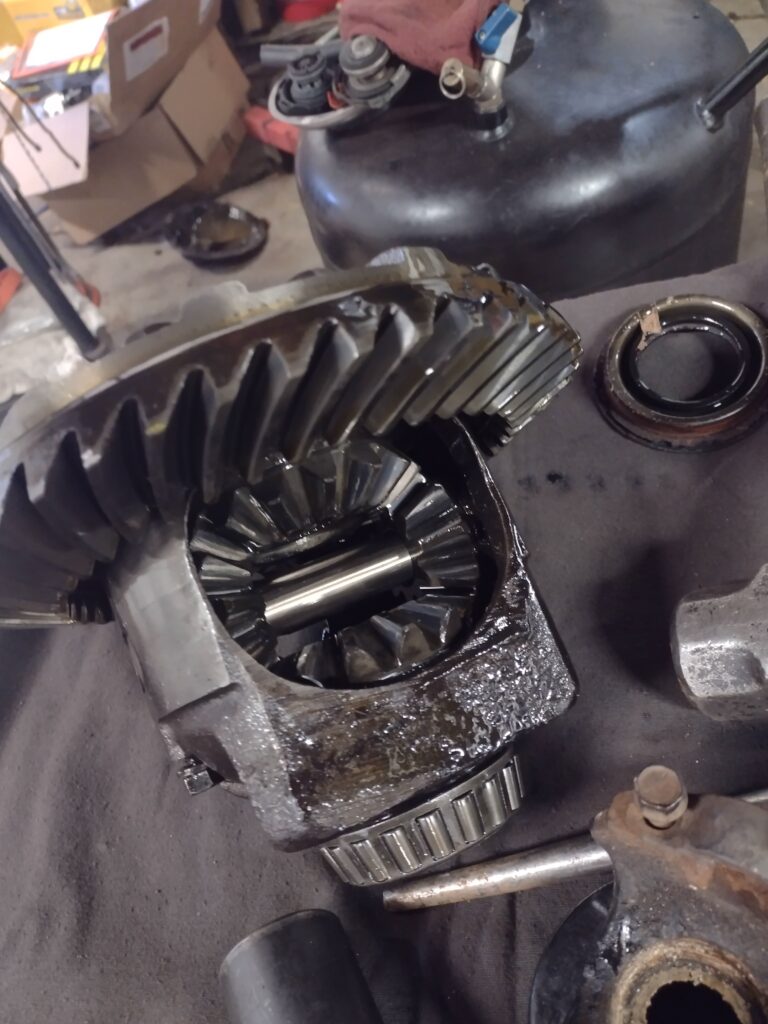
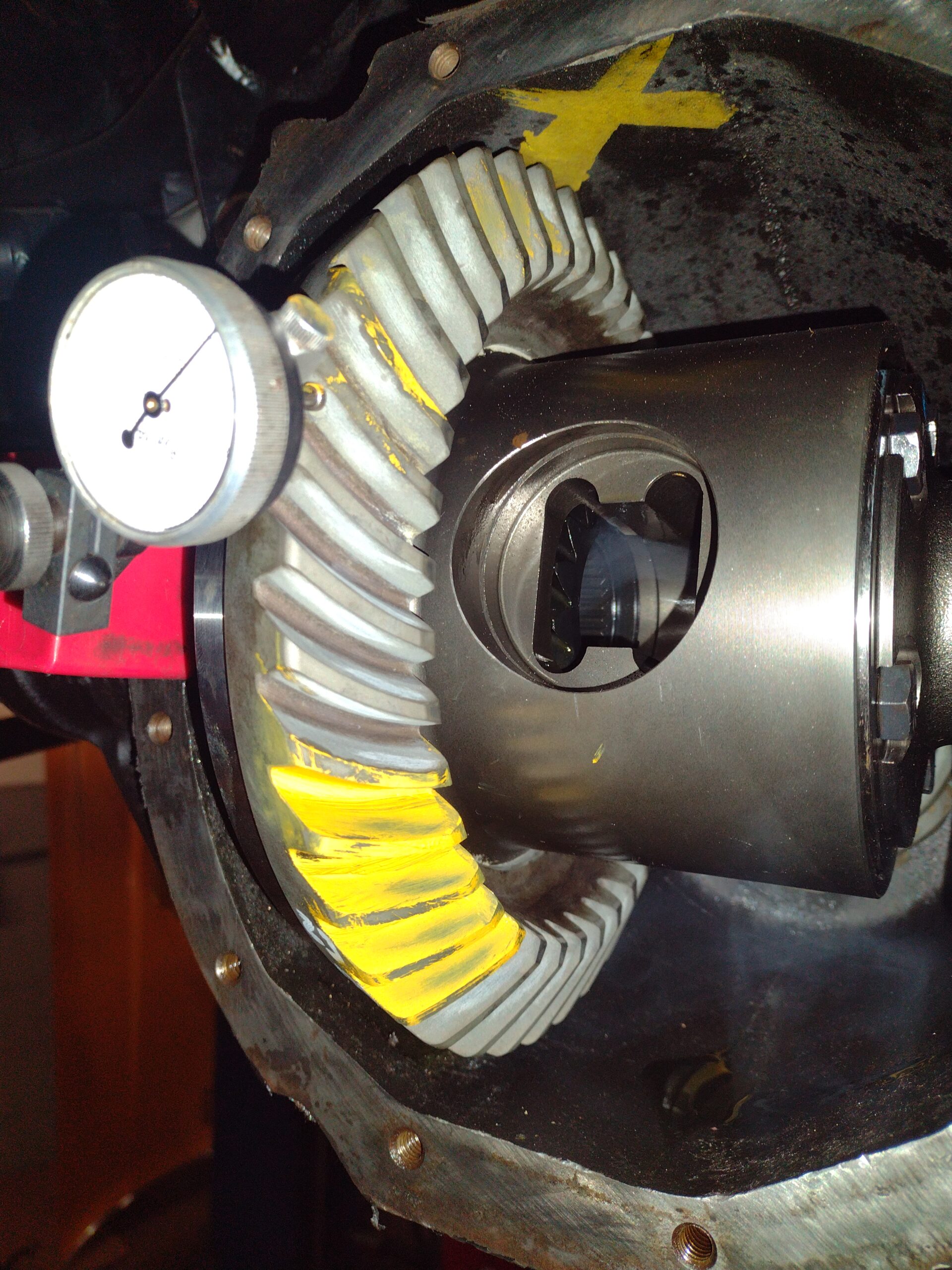
The new gears are assembled to the the true track posi-traction carrier, bearings pressed on to the carrier and the pinion gear and all fitted to the housing. Yellow marking compound is painted on sections of the gear teeth and dial gauge is fitted to check for backlash as shims are set. The marking compound shows the gear mesh pattern as adjustments are made and the setup finalized.
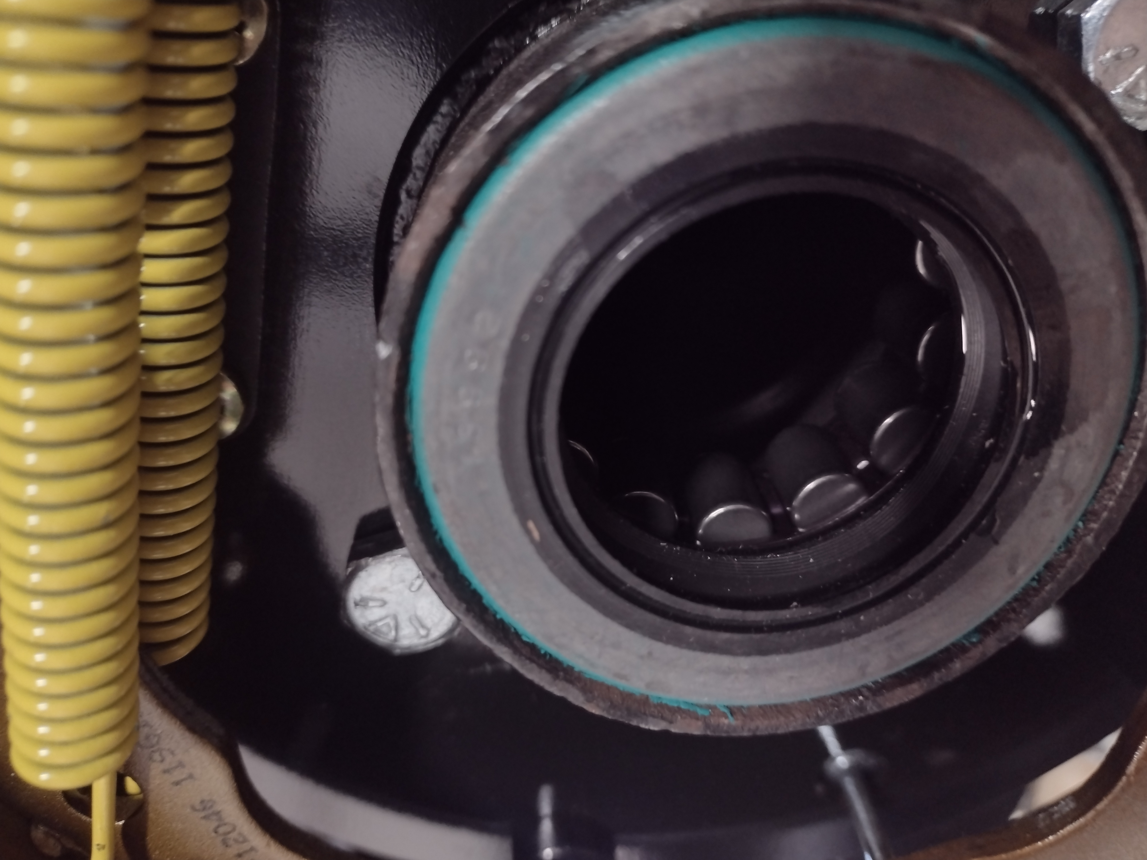
New wheel bearings and seals are installed along with new backing plates and the drum parking brake that will reside inside the rotor hat. The setup of the calipers was very time consuming and iterative as there are 3 bolts for each caliper to mounting plate and each must be shimmed with a combination of washers to ensure that the caliper is centered to the rotor and completely parallel. If not properly set up, the brake pads will not wear squarely.
The new Yukon gear axles are installed. These shipped with two stud patterns – the pressed in 7/16″ studs shown will be knocked out in favor of the screw in 1/2″ studs that match the front hubs.
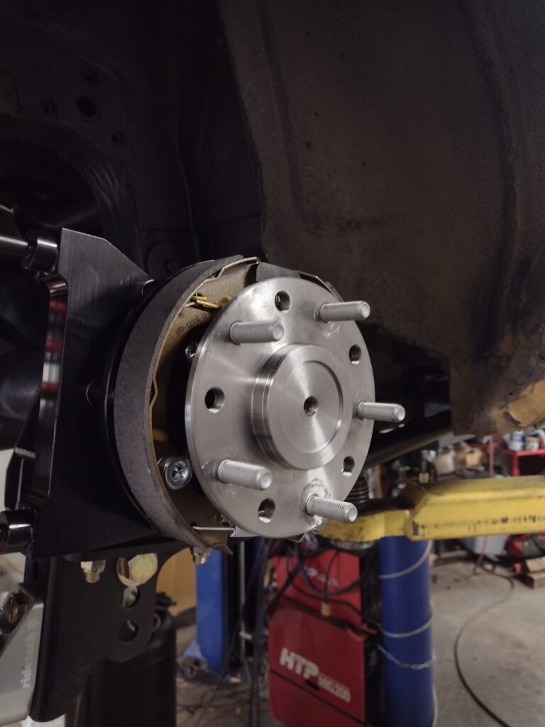
After a number of shim iterations on both sides, the calipers are properly aligned to the rotors and the completed assembly is installed. This was particularly time consuming because one of the three bolts was inaccessible due to the lower spring mount and so the 4 bolts that secure the entire assembly inside the brake shoe area behind the axle had to be removed to allow the entire assembly to rotate 90 degrees clockwise to adjust the shims and reinstall the bolts, the rotating back and re-installing the 4 bolts, with repeated measurements at 3 points to check alignment with the rotor. This can take a couple of hours of adjustment after all the preliminary assembly has already been completed (building the multi-piece rotors), and is a reason why this particular rear brake setup is not the same as bolting on a set of pads and rotors in your driveway on a Saturday afternoon.
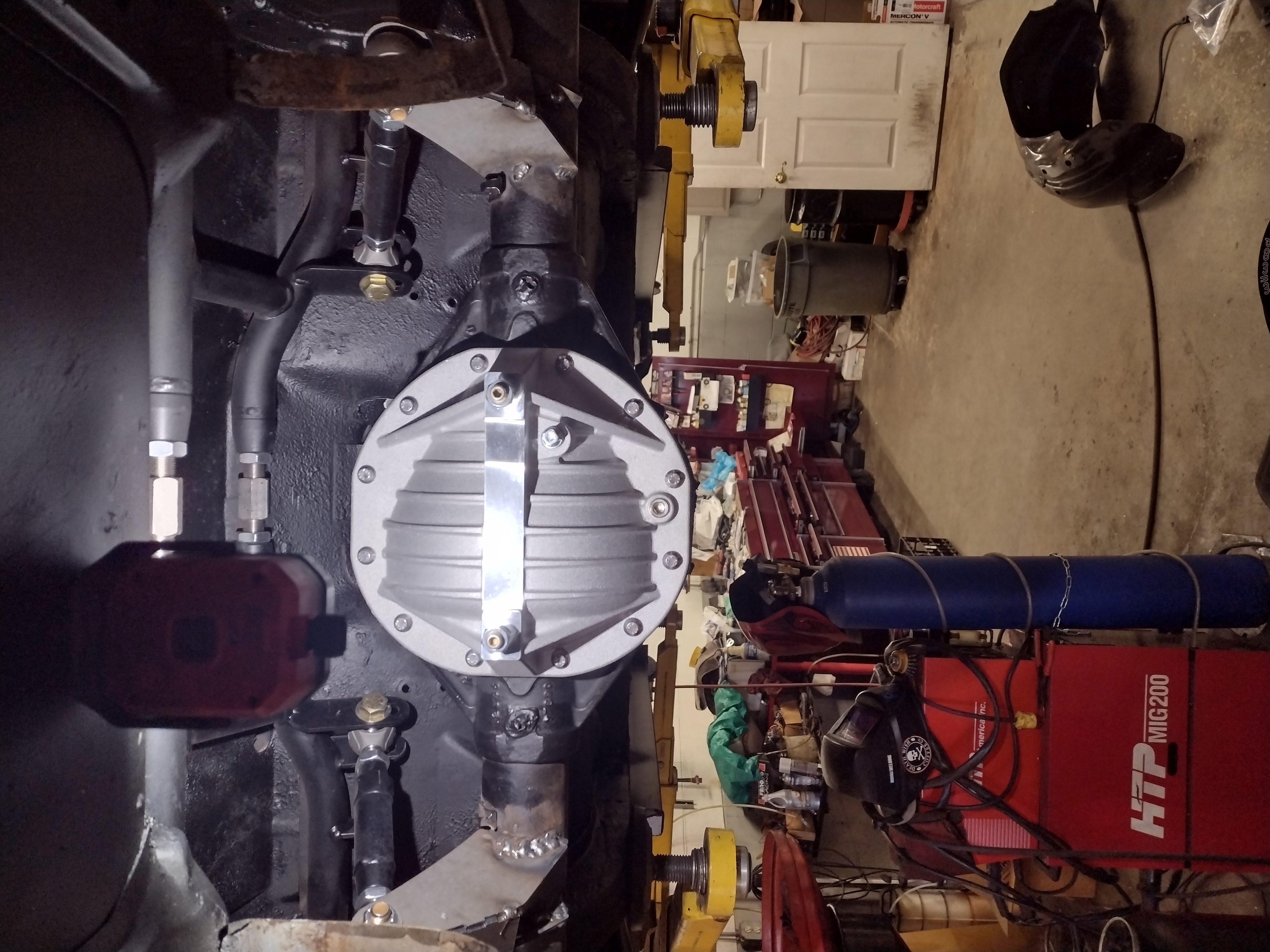
Here the rear is assembled and ready to be filled with oil once we have verified the placement of the upper mounts on the alignment machine and fully seam welded and repainted these areas. We fitted a new aluminum rear axle cover that includes fins to help cool the differential oil and a rear bearing cap brace to strengthen the diff assembly.
In Part 3, we will run all new brake lines, connect the emergency brake system, install a new quick ratio steering box (3 turns lock to lock), fit all new steering components and install some beefy anti-sway bars along with new wheels and tires to get us ready to roll onto the alignment rack.